Image processing apparatus and control method thereof
a technology of image processing and control method, applied in the field of image processing technique, can solve the problems of inability to accurately estimate the color of light source, the difference between pixels belonging to different objects, and the inability to accurately estimate conventional methods
- Summary
- Abstract
- Description
- Claims
- Application Information
AI Technical Summary
Benefits of technology
Problems solved by technology
Method used
Image
Examples
first embodiment
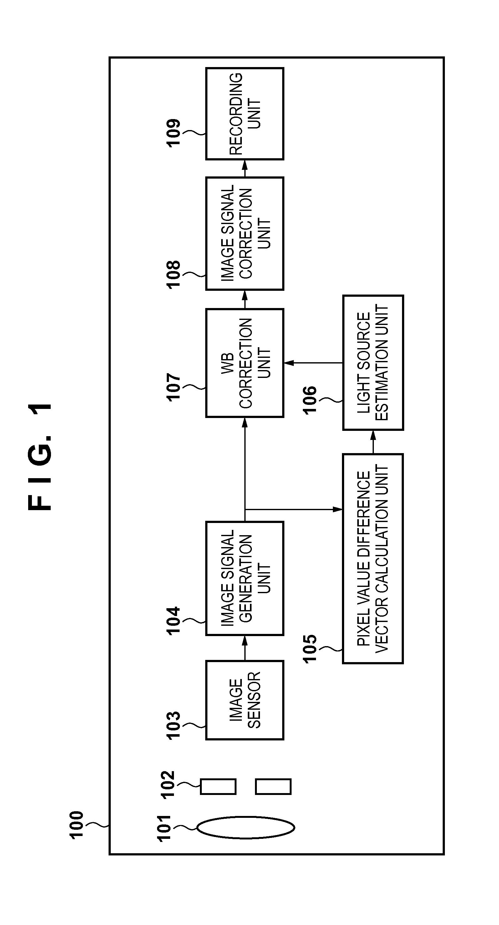
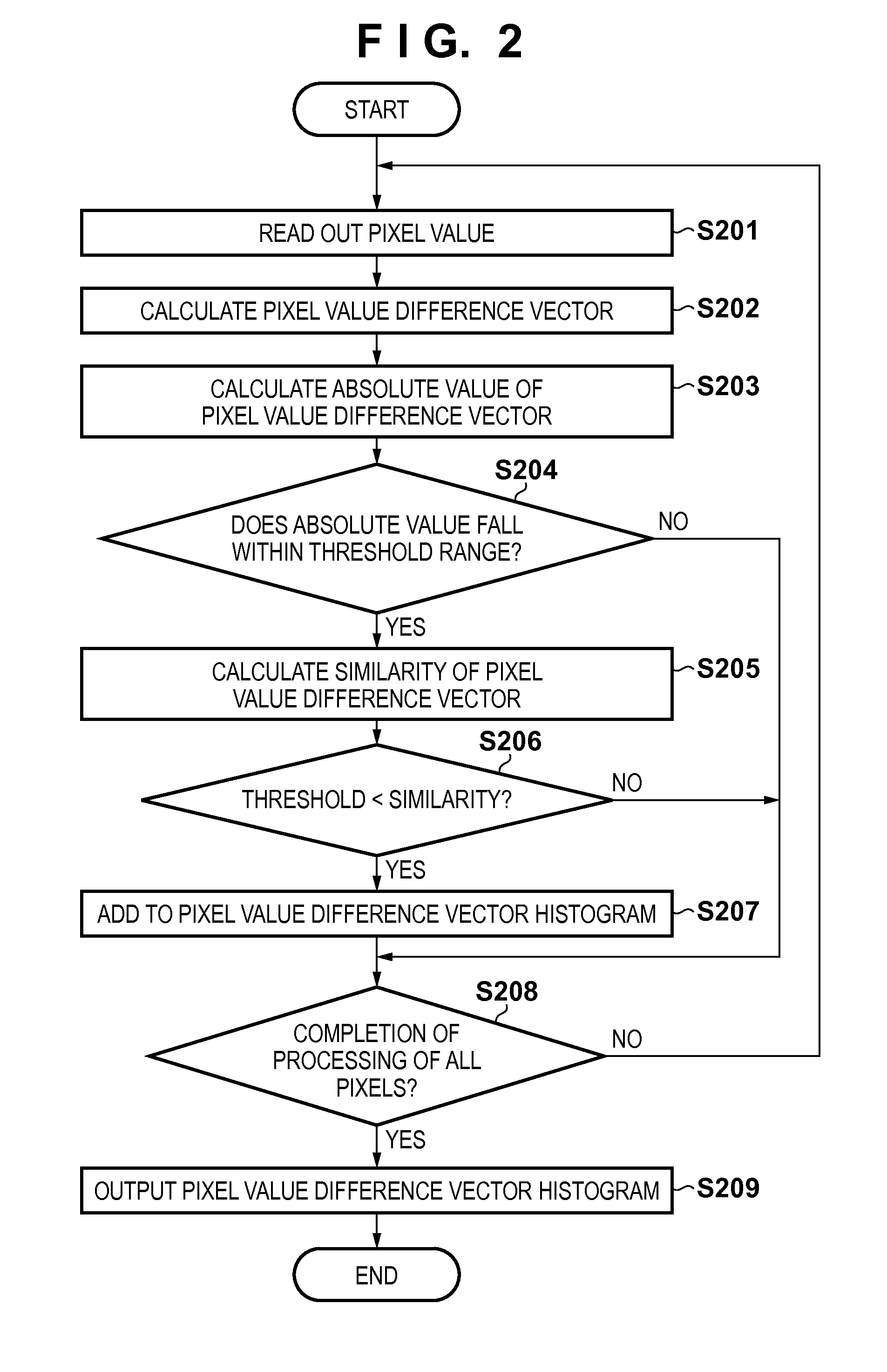
[0042]An image processing apparatus according to the first embodiment will be described below with reference to FIGS. 1 to 5. FIG. 1 is a block diagram showing the arrangement of an image capturing apparatus as an example of an image processing apparatus including a light source estimation function according to the first embodiment. Referring to FIG. 1, an image capturing apparatus 100 includes the following arrangement in addition to a lens 101 and shutter 102. An image sensor 103 converts incoming light into an electrical signal. An image signal generation unit 104 generates image signals (R, G, and B) of an input image. A pixel value difference vector calculation unit 105 calculates a difference value between image signals. A light source estimation unit 106 estimates a color of a light source which illuminates an object in an input image, and calculates a white balance gain. A WB correction unit 107 applies white balance correction to image signals based on the set white balance...
second embodiment
[0072]As the second embodiment of the present invention, a case will be described below wherein a reduced image obtained by reducing an input image is used upon calculation of pixel value difference vectors.
[0073]FIG. 6 shows the arrangement according to the second embodiment. The same reference numerals denote the same units as those in the arrangement according to the first embodiment shown in FIG. 1, and a description thereof will not be repeated. In FIG. 6, a reduced image generation unit 601 and reduced image buffer 602 are added.
[0074]The reduced image generation unit 601 generates a reduced image obtained by reducing an input image generated by an image signal generation unit 104 using a known method. The reduced image buffer 602 records reduced image data generated by the reduced image generation unit 601.
[0075]An overview of an operation of an image capturing apparatus according to the second embodiment will be described below. As in the first embodiment, when the user pres...
third embodiment
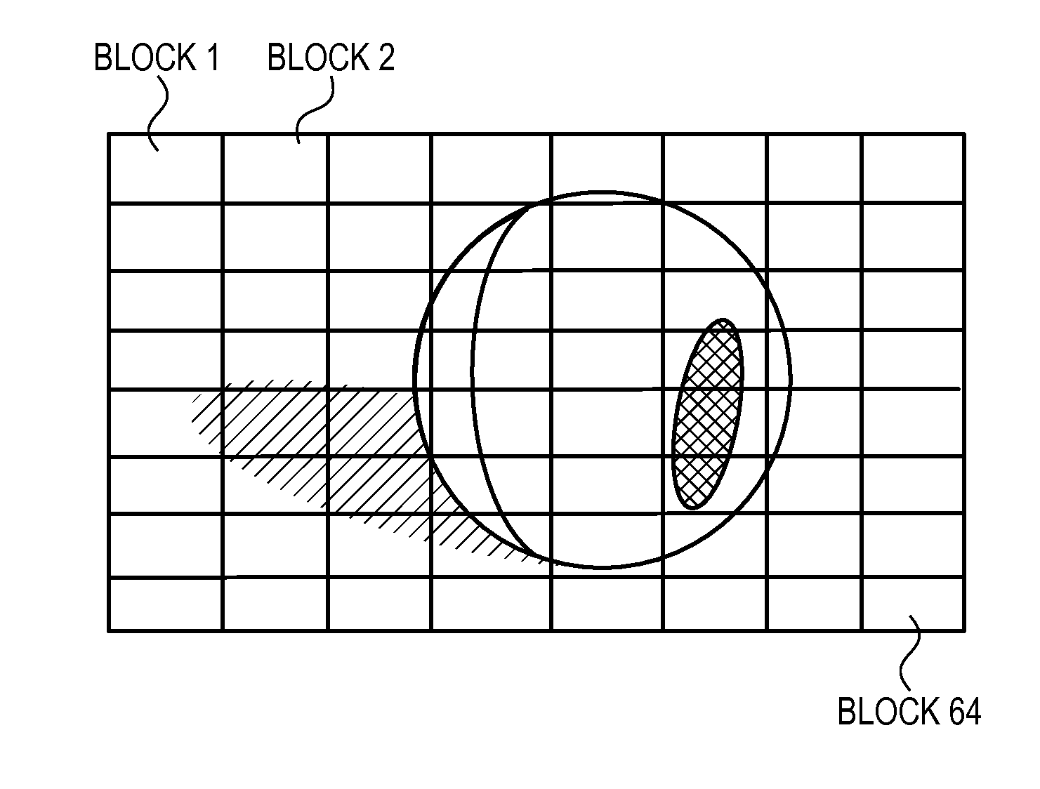
[0079]As the third embodiment of the present invention, a case will be described wherein effective pixel determination also uses conditional determination for respective small blocks obtained by dividing an input image in addition to determination using similarities for respective pixels.
[0080]FIG. 7 shows the arrangement of an image capturing apparatus according to the third embodiment. The same reference numerals denote the same units as those in the arrangement of the first embodiment shown in FIG. 1, and a description thereof will be omitted. In FIG. 7, a block division unit 701 is newly added. The block division unit 701 divides an input image generated by an image signal generation unit 104 into a plurality of blocks.
[0081]Light source estimation processing according to the third embodiment will be described below with reference to FIGS. 8 and 9. FIGS. 8 and 9 are flowcharts respectively showing the processes to be executed by a pixel value difference vector calculation unit 1...
PUM
 Abstract
Description
Claims
Application Information
 - R&D
- Intellectual Property
- Life Sciences
- Materials
- Tech Scout
- Unparalleled Data Quality
- Higher Quality Content
- 60% Fewer Hallucinations
Browse by: Latest US Patents, China's latest patents, Technical Efficacy Thesaurus, Application Domain, Technology Topic, Popular Technical Reports.
© 2025 PatSnap. All rights reserved.Legal|Privacy policy|Modern Slavery Act Transparency Statement|Sitemap|About US| Contact US: help@patsnap.com


