Slotting cutter, cutting insert and tool therefor

a cutting insert and cutting tool technology, applied in the direction of shaping cutters, turning machine accessories, manufacturing tools, etc., can solve the problems of not allowing pocket wear or manufacturing dimensional variations of inserts and pockets, and the tendency of cutting inserts to move in the pock

Active Publication Date: 2013-12-26
KENNAMETAL INC
View PDF16 Cites 6 Cited by
  • Summary
  • Abstract
  • Description
  • Claims
  • Application Information

AI Technical Summary

Benefits of technology

[0005]The problem of minimizing movement of the cutting insert in the pocket during cutting operations has been solved by providing an angled clamping surface on the top surface of the cutting insert that cooperates with a cantilevered member of the cutter body having progressively larger radii forming a spiral shape to distribute stress encountered by the cutting insert during cutting operations.

Problems solved by technology

The existing pocket designs are completely dependent on the spring ability of the cutter body to securely clamp the insert, and does not allow for pocket wear or manufacturing dimensional variations of the insert and pocket.
It has been observed with existing pocket designs that the cutting insert has a tendency to move in the pocket during cutting operations.

Method used


Image

  • Slotting cutter, cutting insert and tool therefor
  • Slotting cutter, cutting insert and tool therefor
  • Slotting cutter, cutting insert and tool therefor

Examples


Embodiment Construction

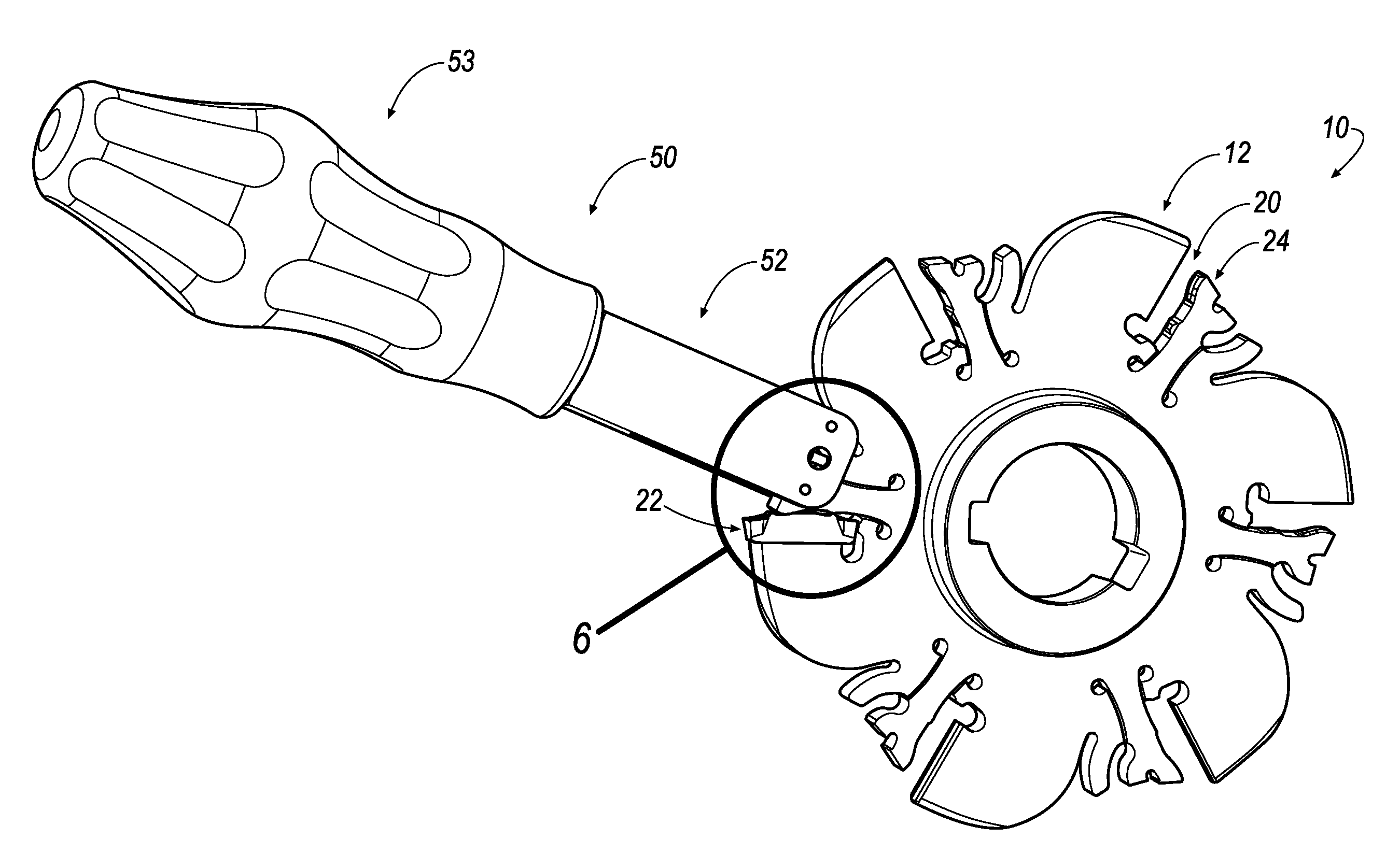
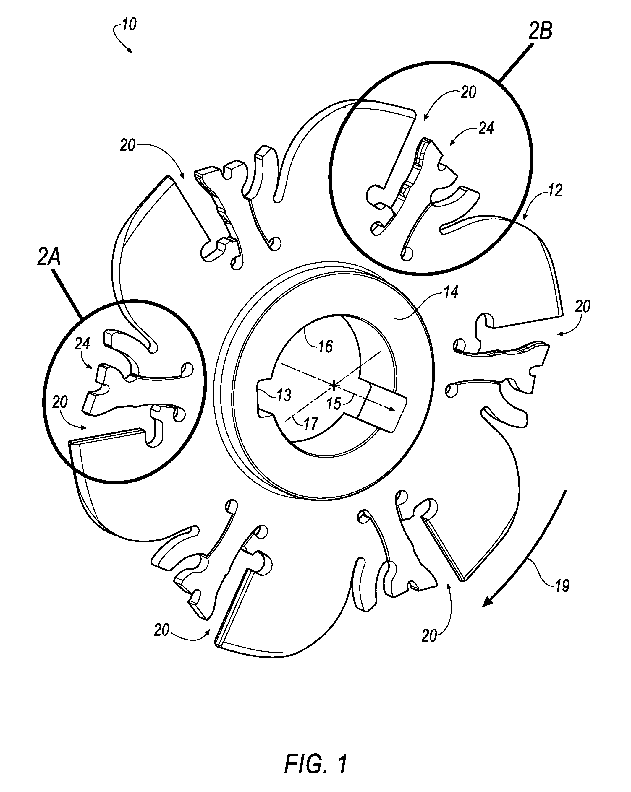
[0025]Referring now to FIGS. 1, 2A and 2B, a slotting cutter 10 is shown according to an embodiment of the invention. The slotting cutter 10 includes a disc-like cutter body 12 having a central hub region 14 that is provided with a bore 16 for receiving a support shaft. The slotting cutter 10 rotates on a central axis 15 perpendicular to a plane 17 of the cutter body 12 in a predetermined direction (indicated by the arrow 19). The central hub region 14 may also be provided with an optional keyway (13) for receiving a drive key (not shown).

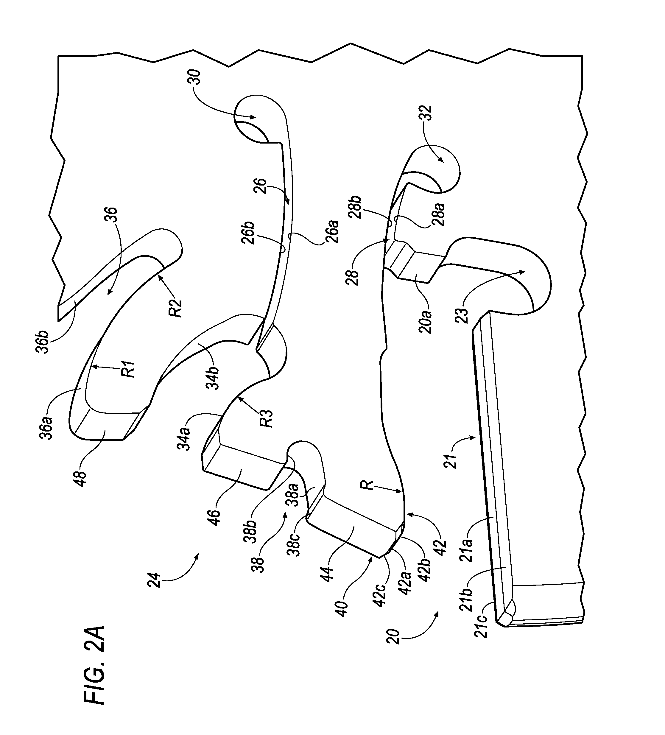
[0026]The slotting cutter 10 is provided with a plurality of pockets 20 formed about the perimeter of the slotting cutter 10 that are capable of receiving a cutting insert 22 (FIGS. 5 and 6). In FIGS. 1, 2A and 2B, the cutting insert 22 is not shown in the slotting cutter 10 for clarity. It will be appreciated that most any suitable number of pockets 20 may be formed about the perimeter of the cutter body 12, depending on the desired material of th...


PUM

PropertyMeasurementUnit
diameteraaaaaaaaaa
diameteraaaaaaaaaa
widthaaaaaaaaaa

Abstract

A slotting cutter includes a disc-like cutter body rotatable in a predetermined direction on a central axis perpendicular to a plane of the cutter body. The cutter body includes a stop slot, an upper cam slot and a lower slot. A plurality of pockets adapted to receive a cutting inset are formed about a perimeter of the body. A cantilevered clamping member includes a bottom surface with a pair of clamping surfaces that engage a pair of angled clamping surfaces on a top surface of the cutting insert during operation. A wrench is provided to lift the cantilevered clamping member for inserting, indexing or removing the cutting insert from the slotting cutter. The wrench includes two fixed pins and a floating pin that prevents the cantilevered clamping member from bending too far and limiting the useful life of the slotting cutter.

Description

BACKGROUND OF THE INVENTION[0001]Slotting cutters are known for cutting keyways and the like and, also, for providing work members with slots of various width. Slotting cutters are somewhat similar to milling cutters in that the cutter usually employs a disc-like member having cutting inserts mounted in the periphery thereof. In a milling cutter, the cutting inserts are generally presented axially, whereas, in a slotting cutter, the cutting inserts protrude radially from the supporting disc and are, thus, presented to the work in the radial direction.[0002]In order to form slots rapidly and efficiently, it is desirable that the cutting inserts be solidly supported in the cutter body and have adequate clearance between the cutting edges of the inserts and the cutter body as the material is removed from the work piece. With the inserts solidly supported and having sufficient clearance between the cutter body and the cutting edges, the slotting cutter is able to withstand substantial l...

Claims


Application Information

Patent Timeline
Patent Type & Authority Applications(United States)
IPC IPC(8): B23C5/08B23C5/22
CPCB23B27/045B23B2260/0785B23C5/08B23C5/2247B23C2210/161Y10T407/1942Y10T407/2286Y10T407/2288Y10T407/235
Inventor WAGGLE, JAMES MICHAELGAMBLE, KEVIN MICHAEL
Owner KENNAMETAL INC
Why Eureka
Try Eureka