Multi-speed gear system

a multi-speed, hub technology, applied in the direction of toothed gearings, belts/chains/gearings, transmission elements, etc., can solve the problems of increasing the size and overall weight of the hub casing, and the rigidity of the 5 mm through-bolts used today for non-load bearing quick release bolts, which are insufficient for shear force load carrying

Active Publication Date: 2013-12-26
CA TECH SYST
View PDF4 Cites 5 Cited by
  • Summary
  • Abstract
  • Description
  • Claims
  • Application Information

AI Technical Summary

Benefits of technology

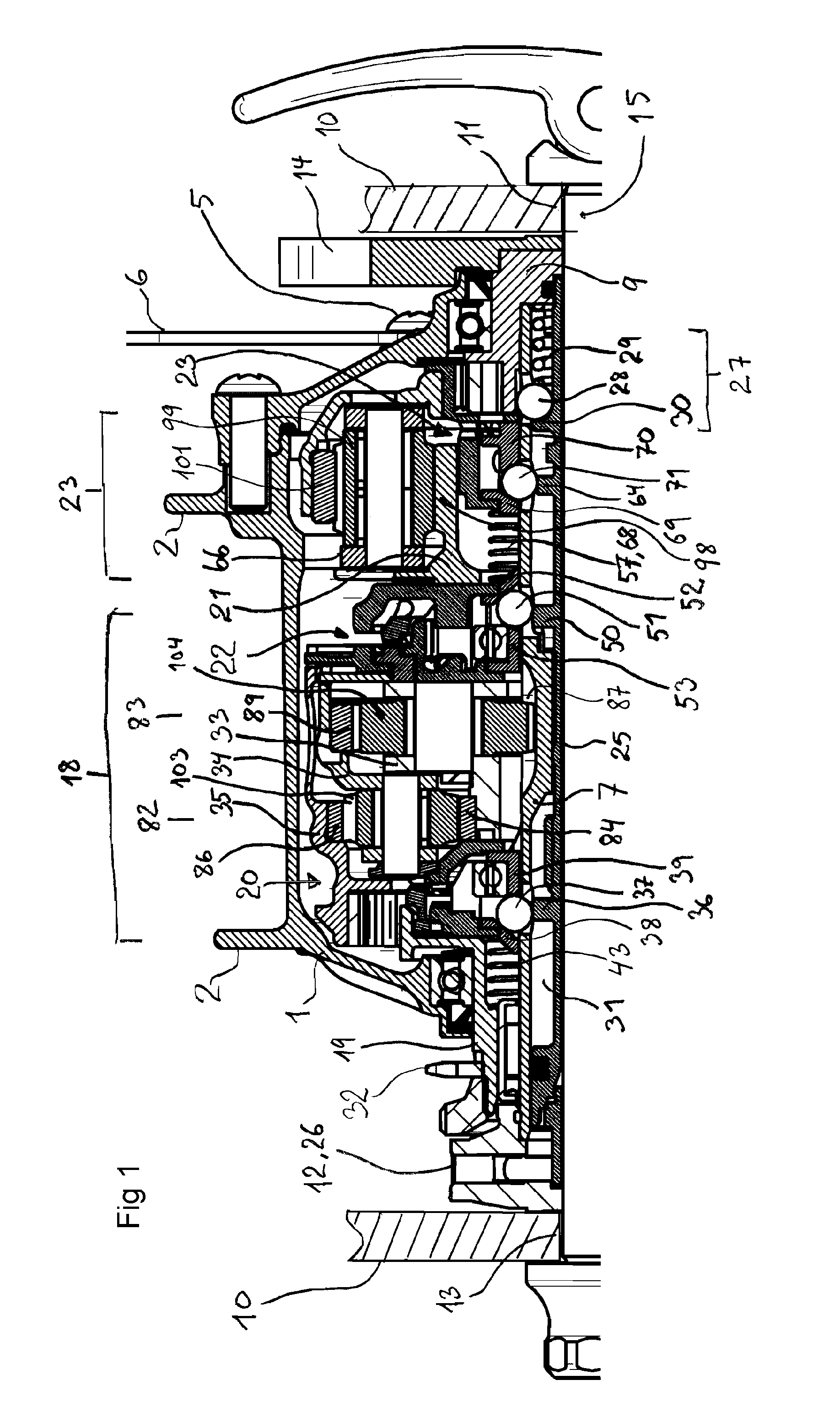
[0015]An objective of the present invention is to provide an enclosed speed change gear unit, with key features enabling the unit to be considered attractive for active use in rough terrain. It should at least offer a large number of alternative speeds and a broad overall gear width, a compact and light weight design, a rigid interface to the vehicle, and user friendly means for hub to frame de / attachment.

Problems solved by technology

The use of such through-bolt requires redesign of the epicyclical mechanisms and moving of the centrally located shift mechanisms radially towards the hub shell, which unless mitigated by a favourable redesign of the structure, causes an increase in hub casing size and overall weight.
While definite measures of the minimum diameter sufficient for high performance are not available, it is widely considered that the 5 mm through-bolts which are typically used today for non load bearing quick release bolts are insufficiently rigid to be applied as shear force load carrying.

Method used


Image

  • Multi-speed gear system
  • Multi-speed gear system
  • Multi-speed gear system

Examples


second embodiment

[0050]A second embodiment is shown schematically in FIG. 5b and also consists of three epicyclical gear sections; a first epicyclical gear section 90, which has a sun wheel 92, a planet carrier 96, a ring gear 97 and planet gears 111, a second epicyclical gear section 91, which has a sun wheel 95, a planet carrier 96, a ring gear 97 and planet gears 112. The gear sections 90, 91 are coupled as follows; the sun gear 95 of the first epicyclical gear section 90 is non-rotatably connected to the axle 7, the ring gear 97 of the second epicyclical gear section 91 surrounding the first epicyclical gear section 90, the planet carrier 96 of the second epicyclical gear section 91 non-rotatably connected to the ring gear 94 of the first epicyclical gear section 90, and the planet carrier 93 of the first epicyclical gear section 90 non-rotatably connected to the sun wheel 95 of the second epicyclical gear section 91. Alternative speed gear ratios are enabled by selectively connecting the drivin...

third embodiment

[0051]A third embodiment is shown schematically in FIG. 5c, and consists of four epicyclical gear sections; a first epicyclical gear section 82 or 90, has a sun wheel 84 or 92, a planet carrier 85 or 96, a ring gear 86 or 97 and planet gears 103 or 111, a second epicyclical gear section 83 or 91, which has a sun wheel 87 or 95, a planet carrier 88 or 96, a ring gear 89 or 97 and planet gears 104 or 112, a third 113 and fourth epicyclical gear section 114 with a third sun wheel 105 coupled to the second epicyclical gear section 83 or 91 through the intermediate shaft 21, the sun wheel 105 of the third epicyclical section 113, meshing with at least one planet gear 106 of the third epicyclical section 113, the planet gears 106 of the third epicyclical section 113 non-rotatably connected with the planet gears 108 of the fourth epicyclical section 114, meshing with the ring gear 109 of the fourth epicyclical section 114, which is connected with the load bearing internal shaft 7 through a...


PUM


Abstract

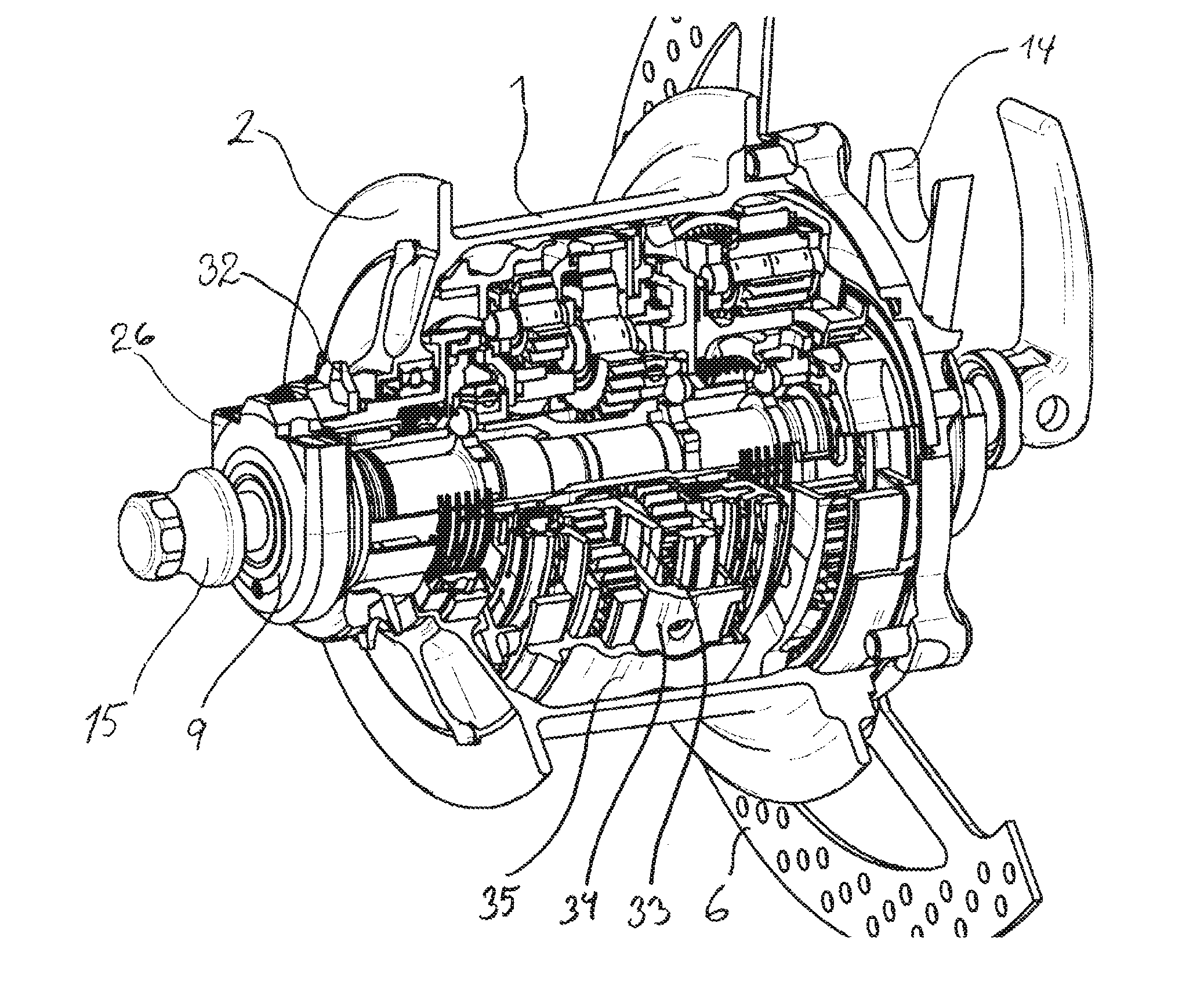
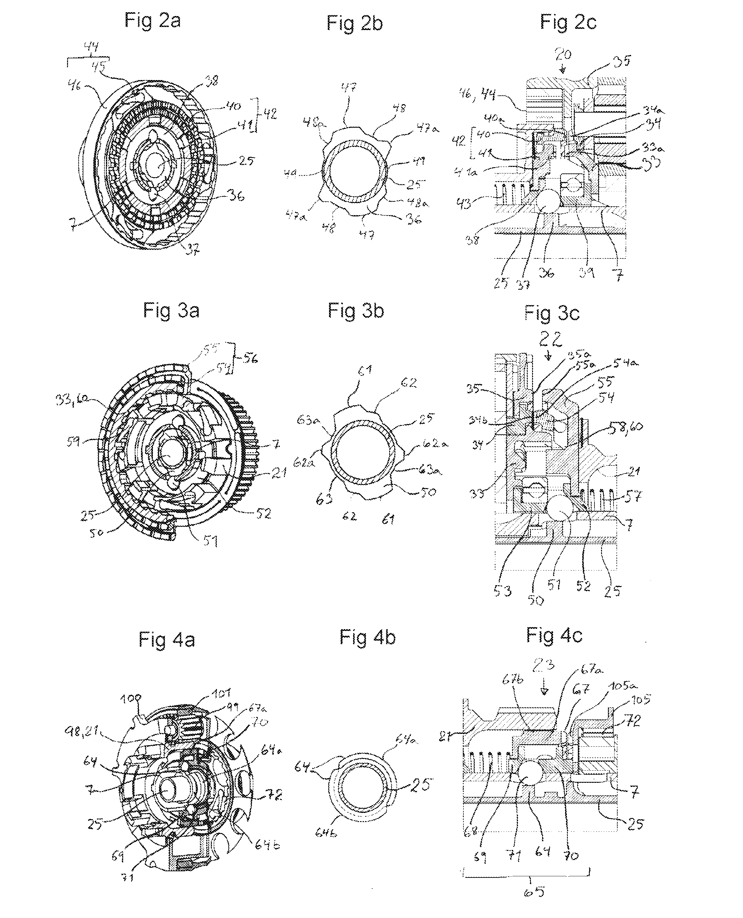
A robust and reliable multi-speed gear system for use on pedally or other manually propelled vehicles, comprising simple epicyclical sections 82, 83, 23 in a complex structure, an internal axial tunnel enabling use of a detachable, vertical shear force load carrying through-bolt 15, a rotatable shift axle 25, a main shaft 7 non-rotatably mounted to the vehicle frame 10, axially floating shift mechanisms 20, 22, 65, and a hub shell 1 fully enclosing the gear mechanisms. The multispeed hub is robust, light, easily manufactured, offers many speeds and great gear width, and is rigidly securable to the vehicle frame.

Description

BACKGROUND OF THE INVENTION[0001]The present invention relates to epicyclical multispeed internally geared hubs for bicycles, tricycles and other wholly or partially pedally or otherwise manually propelled vehicles. The advance of the sport of mountain biking has brought with it a need for gear units with a broad selection of different speeds for use in particularly mountainous terrain, sufficiently robust for use in rough terrain, and with features enabling high performance in competitive application. However, a problem herein lies in that internally geared hubs of today are not in these regards considered attractive. Such hubs are limited by their insufficient robustness, number of speeds, gear width, lateral rigidity, number of gear ratio alternatives, ease of operation, and their complexity and manufacturing costs. The present invention provides a hub gear that overcomes these issues.DESCRIPTION OF PRIOR ART[0002]Rigidity in the rear frame of the pedally propelled vehicle is imp...

Claims


Application Information

Patent Timeline
Patent Type & Authority Applications(United States)
IPC IPC(8): F16H3/78
CPCF16H3/78B62M11/16B62M11/18F16H3/66F16H2200/0043F16H2200/0056F16H2200/201F16H2200/2053F16H2200/2097
Inventor ANTAL, CHRISTIANLJOSNE, KNUT TORE
Owner CA TECH SYST
Why Eureka
Try Eureka