
Thermoelectric module, heat exchanger, exhaust system and internal combustion engine

a technology of heat exchanger and thermal module, which is applied in the direction of thermoelectric devices with peltier/seeback effect, combined combustion mitigation, electric apparatus, etc., can solve the problem of comparatively large effort needed in the manufacture of heat exchangers, and achieve the effect of reducing the risk of destruction or damage to ceramic plates and increasing thermal conductivity

Active Publication Date: 2014-01-02
EBERSPACHER EXHAUST TECH GMBH & CO KG
View PDF3 Cites 10 Cited by
  • Summary
  • Abstract
  • Description
  • Claims
  • Application Information

AI Technical Summary

Benefits of technology

This patent describes a heat exchanger design using ceramic plates that are segmented and fastened to metal bridges. Segmentation reduces pressure peaks and allows for relative movement between the segments. An elastic heat-conducting layer can be added between the ceramic plate and the cooling tube to improve heat transfer and compensate for surface unevennesses. The technical effects are improved heat exchanger performance and reduced pressure peaks.

Problems solved by technology

The effort needed for this during the manufacture of the heat exchangers is comparatively great.

Method used


Image

  • Thermoelectric module, heat exchanger, exhaust system and internal combustion engine
  • Thermoelectric module, heat exchanger, exhaust system and internal combustion engine
  • Thermoelectric module, heat exchanger, exhaust system and internal combustion engine

Examples


Embodiment Construction

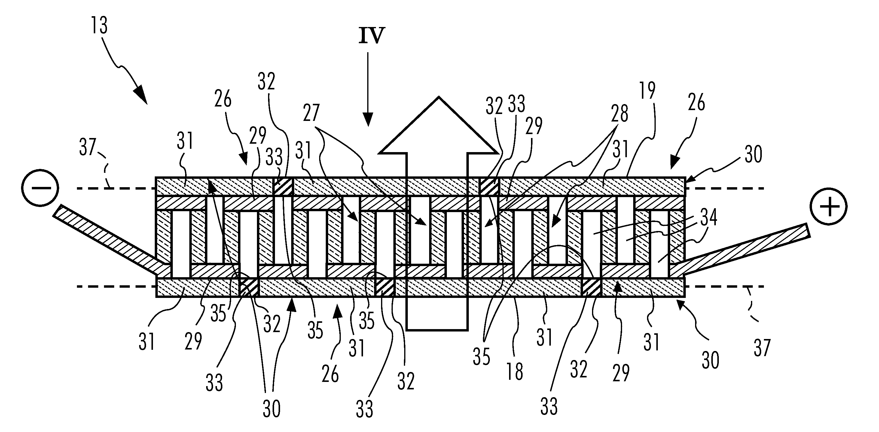
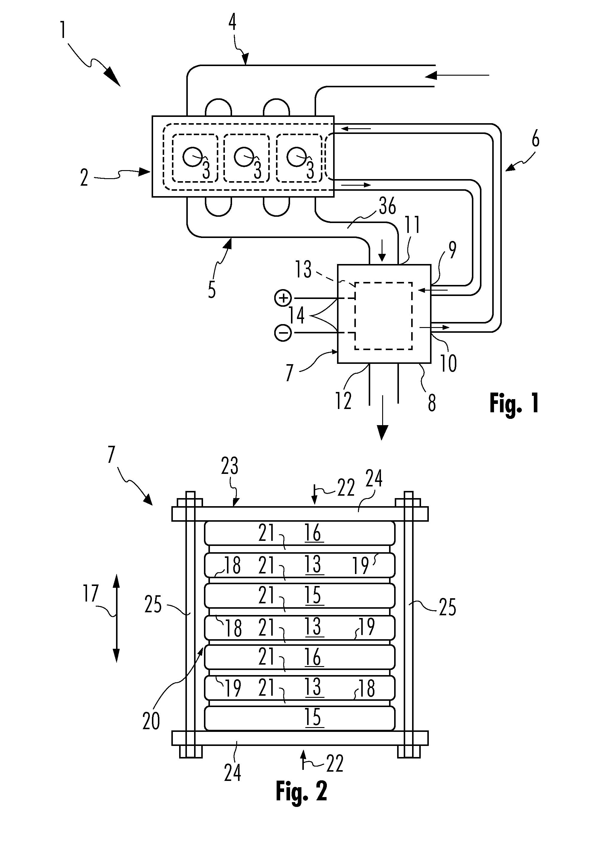
[0034]Referring to the drawings in particular, corresponding to FIG. 1, an internal combustion engine 1, which is preferably used in a motor vehicle, comprises an engine block 2, which contains a plurality of combustion chambers 3, a fresh air supply unit 4 for supplying the combustion chambers 3 with fresh air, and an exhaust system 5 for removing exhaust gas from the combustion chambers 3. Furthermore, the internal combustion engine 1 is equipped with a cooling circuit 6, by means of which the engine block 2 can be cooled. It is clear that a cooler, not shown here, optionally in connection with a blower, may be provided in the cooling circuit 6 in order to be able to correspondingly cool the coolant being carried in the cooling circuit 6. The cooling circuit 6 used to cool the engine block 2 may also be called an engine cooling circuit or a primary cooling circuit. In addition to this primary cooling circuit 6, a separate cooling circuit, not shown here, which may also be called a...


PUM


Abstract

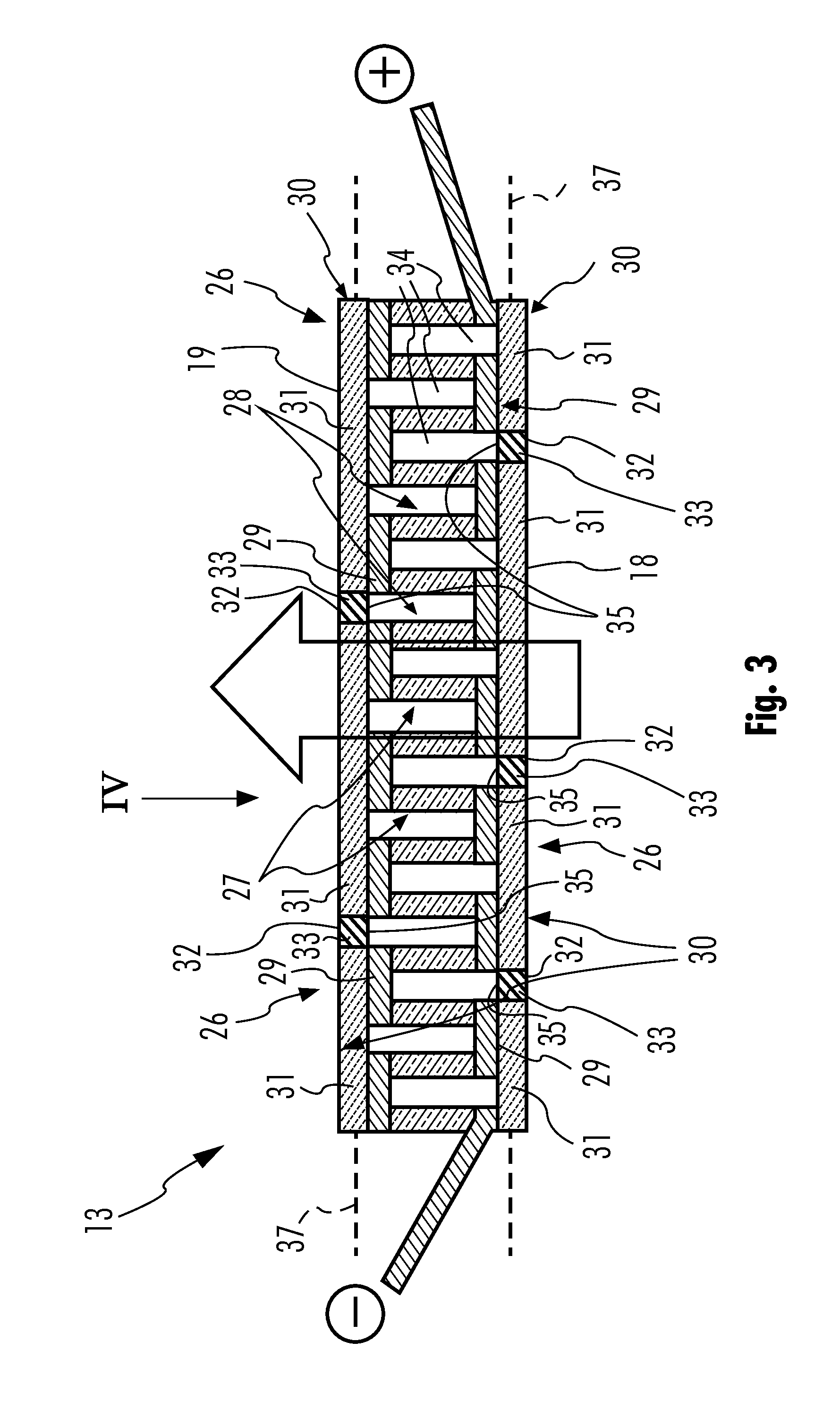
A thermoelectric module (13), for converting thermal energy into electric energy, includes a plurality of leg pairs (26), which have each a p-doped semiconductor leg (27) and an n-doped semiconductor leg (28), which are contacted with one another electrically via metal bridges (29). At least one electrically insulating ceramic plate (30), which is arranged on a hot side (18) of the thermoelectric module (13) or on a cold side (19) of the thermoelectric module (13) and is flatly in contact with metal bridges (29) associated with this side (18, 19) and is fastened thereto. The pressure stability of the thermoelectric module (13) can be improved if the respective ceramic plate (30) is segmented, so that a plurality of ceramic plate segments (31) are arranged next to each other, which are each flatly in contact with a plurality of metal bridges (29) and are fastened thereto.

Description

CROSS REFERENCE TO RELATED APPLICATIONS[0001]This application claims the benefit of priority under 35 U.S.C. §119 of German Patent Application DE 10 2012 210 627.8 filed Jun. 22, 2012, the entire contents of which are incorporated herein by reference.FIELD OF THE INVENTION[0002]The present invention pertains to a thermoelectric module for converting thermal energy into electric energy. The present invention pertains, moreover, to a heat exchanger equipped with at least one such thermoelectric module. The present invention pertains, furthermore, to an exhaust system as well as to an internal combustion engine, which are equipped with such a heat exchanger.BACKGROUND OF THE INVENTION[0003]A thermoelectric module can convert a heat flow into an electric current by utilizing the so-called Seebeck effect. The Seebeck effect is based on an inversion of the Peltier effect. Such thermoelectric modules can therefore be used to recover heat or to generate electric energy from heat and can be ...

Claims


Application Information

Patent Timeline
Patent Type & Authority Applications(United States)
IPC IPC(8): H01L35/32H01L35/04H10N10/13H10N10/17H10N10/81
CPCH01L35/32H01L35/04Y02E20/14H10N10/81H10N10/17
Inventor OESTERLE, JORGSPIETH, ARNULFRESCH, ANDREASTCHAMGOUE, HERVELEICHT, SEBASTIAN
Owner EBERSPACHER EXHAUST TECH GMBH & CO KG
Learn More