Tamping assembly for a track tamping machine

a technology of track tamping machine and assembly, which is applied in the direction of mechanical equipment, servomotors, ways, etc., can solve the problems of increasing the size and cost of special cylinders, a disadvantage in increasing the size of cylinders, and b lines of hydraulic valves

Active Publication Date: 2021-01-14
HP3 REAL GMBH
View PDF12 Cites 1 Cited by
  • Summary
  • Abstract
  • Description
  • Claims
  • Application Information

AI Technical Summary

Benefits of technology

[0021]During the tamping, the tamping picks plunge into the ballast 4 of a track 1 and compact the ballast 4 under the sleepers 2. The sleepers 2 are fastened on the rails 6. The tamping arms 3 are articulated on the tamping box 7. The tamping box 7 is moved up and down on vertical guides 8 via a drive 9. In the figure, according to the invention, the mechanical hydraulic cylinder actuation valve part 12 is constructed separately from the shock-sensitive valve electronic unit 13. A control and regulation electronic unit 14 is connected to the distance sensors 17 via electrical connecting lines 16. In addition, the valve electronic parts 13 are actuated via the control lines 15. The control valve parts 12 which are directly in the special cylinder 11 are supplied using the pressure line P and the tank line T.

Problems solved by technology

Another disadvantage is that the A, B lines of the hydraulic valve have to be integrated directly into the cylinder as boreholes.
The size and the costs of the special cylinder thus increase.
The increasing size of the cylinder is a disadvantage with respect to the constricted space conditions in tamping assemblies.
In addition, high pressure variations occur at the pressure lines and tank lines of the control valve, which additionally stress the control valve.
This results in a reduction of the lifetime and also in the challenge of keeping the hydraulic screw connections leak-tight in the long term.

Method used


Image

  • Tamping assembly for a track tamping machine
  • Tamping assembly for a track tamping machine

Examples


Embodiment Construction

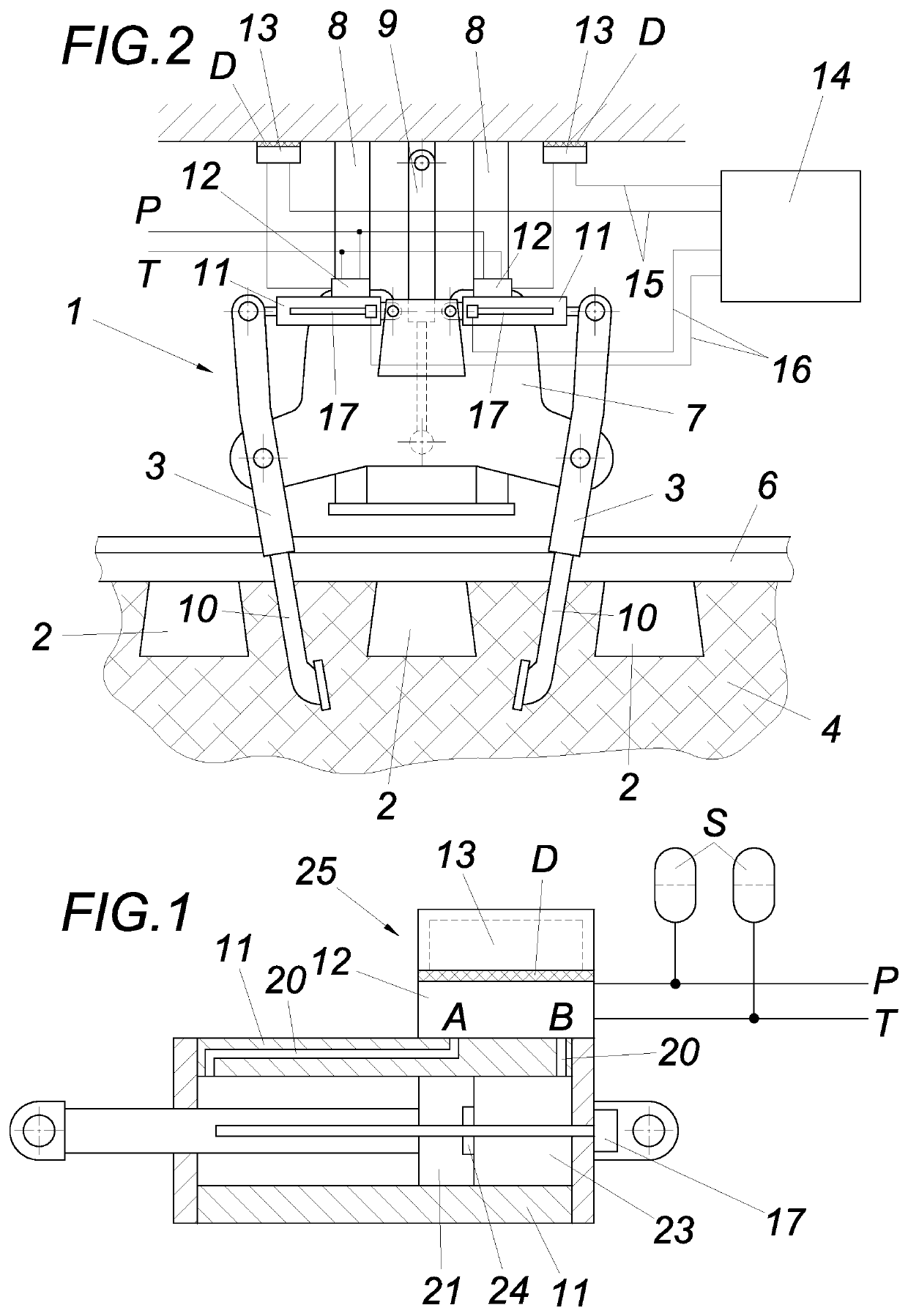
[0007]The invention is thus based on the object of refining tamping assemblies of the type described at the outset using simple means in such a way that the durability of the fully hydraulic tamping drive is significantly increased.

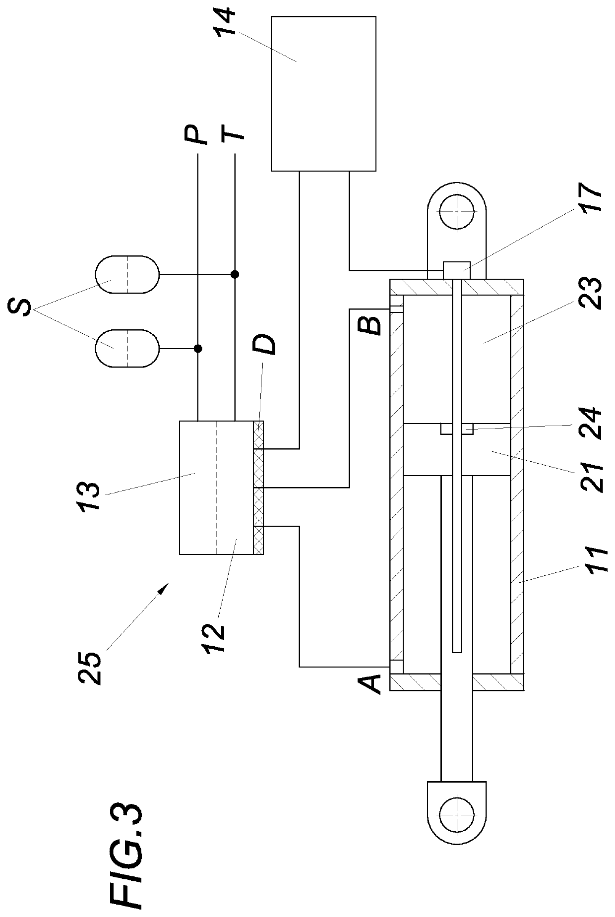
[0008]The invention achieves the stated object in that the valve electronic unit is mounted in a vibration-damped manner with respect to the hydraulic cylinder and / or the mechanic hydraulic cylinder actuation valve part by means of vibration dampers.

[0009]The valve electronic unit of the hydraulic control valve is constructed separately from the (electro-)mechanical part of the hydraulic control valve. The valve electronic unit can thus be mounted in a vibration-damped manner with respect to the hydraulic cylinder and / or the mechanical hydraulic cylinder actuation valve part. The vibration-damping mounting can be formed by corresponding rubber-elastic elements, by spring damper elements, or the like. The durability of the fully hydraulic tamping drive is ...


PUM


Abstract

A tamping assembly (1) for a track tamping machine is proposed comprising tamping tool pairs (3), which are arranged on a girder (7) guided vertically adjustable in a tamping assembly frame and are formed as swing arms, and the lower tamping pick ends (10) of which intended for plunging into a ballast bed (4) are drivable using an oscillation drive and are hydraulically closable toward one another, wherein a hydraulic cylinder (11) and possibly a distance sensor (7) for determining the hydraulic cylinder position are associated with each of the tamping tools (3) of a tamping tool pair, and the hydraulic cylinders (11) form both the linear closing drive and also the oscillation drive of the tamping tools (3), and wherein electrohydraulic valves (25) are provided for actuation of the hydraulic cylinders (11), which comprise a mechanical hydraulic cylinder actuation valve part (12) and an associated valve electronic unit (13). To provide advantageous construction conditions, it is proposed that the valve electronic unit (13) is mounted in a vibration-damped manner by means of vibration dampers (D) with respect to the hydraulic cylinder (11) and/or the mechanical hydraulic cylinder actuation valve part (12).

Description

TECHNICAL AREA[0001]The invention relates to a tamping assembly for a track tamping machine having tamping tool pairs, which are arranged on a girder guided vertically-adjustable in a tamping assembly frame and are formed as rocker arms, and the lower tamping pick ends of which, which are intended to plunge into a ballast bed, are drivable using an oscillating drive and can be hydraulically closed toward one another, wherein a hydraulic cylinder and possibly a distance sensor for determining the hydraulic cylinder position are associated with each of the tamping tools of a tamping tool pair, and the hydraulic cylinders form both the linear closing drive and also the oscillating drive of the tamping tools, and wherein electrohydraulic valves are provided for actuating the hydraulic cylinders, which comprise a mechanic hydraulic cylinder actuation valve part and an associated valve electronic unit.PRIOR ART[0002]Tamping assemblies penetrate the ballast of a rail bed using tamping tool...

Claims


Application Information

Patent Timeline
Patent Type & Authority Applications(United States)
IPC IPC(8): E01B27/16F15B1/02F15B11/16F15B15/28F15B15/06F15B21/00
CPCE01B27/16F15B1/02F15B11/16F15B15/28F15B2211/71F15B21/008E01B2203/12F15B2211/212F15B15/06B07C5/368
Inventor LICHTBERGER, BERNHARD
Owner HP3 REAL GMBH
Why Eureka
Try Eureka