Buffer cylinder

A buffer cylinder and buffer cavity technology, applied in the field of hydraulic cylinders, can solve the problems of shortening the service life of the cylinder, large impact of the cylinder, and affecting the buffering effect, etc., and achieve the effects of smooth pressure transition, increased life, and reduced pressure peaks

Active Publication Date: 2016-08-24
LIUZHOU LIUGONG HYDRAULIC COMPONENTS +1
View PDF8 Cites 3 Cited by
  • Summary
  • Abstract
  • Description
  • Claims
  • Application Information

AI Technical Summary

Problems solved by technology

[0004] The purpose of the present invention is to provide a buffer oil cylinder, which can solve the problem that the buffer structure of the existing oil cylinder has eccentricity, which causes wear and affects the buffer effect, and causes the instantaneous impact of the oil cylinder to be too large and greatly reduces the service life of the oil cylinder.

Method used


Image

  • Buffer cylinder
  • Buffer cylinder
  • Buffer cylinder

Examples


Embodiment 1

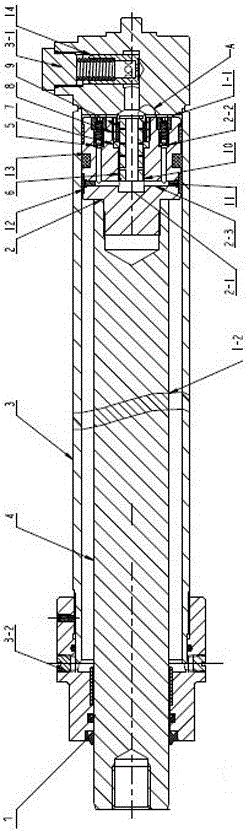
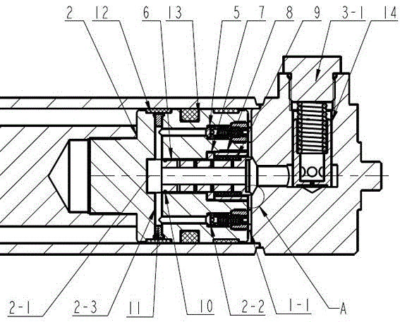
[0021] figure 1 The buffer cylinder shown is a lifting cylinder for a forklift, which mainly includes a cylinder head 1, a cylinder body 3, a cylinder head 14, a piston rod 4, a piston 2, a one-way valve 2-2, a buffer plunger 6 and a spring 9. The cylinder head 1 and the cylinder head 14 are respectively installed on both ends of the cylinder body 3, one end of the piston rod 4 extends into the cylinder body 3 through the through hole in the middle of the cylinder head 1, and the other end is exposed outside the cylinder, and the piston rod 4 is set to The extension direction of the rod 4 is the front, and it is the rear anyway. The piston rod 4 and the cylinder head 1 seal the cylinder mouth of the cylinder body 3 together, and the piston 2 is connected with one end of the piston rod 4 placed in the cylinder body 3. The inner chamber of the body 3 is separated to form a rod chamber 1-2 and a rodless chamber 1-1. The cylinder head 1 is provided with a large chamber oil port 3-...

Embodiment 2

[0024] In this example, the first unilateral gap between the buffer plunger and the buffer cavity is a=0.5 mm; the snap ring and the buffer cavity are clearance fit, and the second unilateral gap is b=0.05 mm; the retaining ring and the buffer plunger are clearance fit, Its fit gap c=0.01 mm; in the same oil cylinder, the relationship of the three fit gaps is a>b>c; a check valve is installed in the piston close to the side of the rodless chamber, the one-way valve of this embodiment The valve is a ball valve, and the number of one-way valves is one. Each one-way valve is connected to the buffer cavity through a drainage hole. The rodless cavity and the small hole in the axial through hole, the small hole is a radial small hole opened radially inward from the outer surface of the buffer plunger, the number of the small hole is 1, and the diameter of the small hole is 5mm; the piston and the cylinder The seal between the internal walls adopts the sealing form of setting a seali...

Embodiment 3

[0026] In this example, the first unilateral gap between the buffer plunger and the buffer cavity is a=3 mm; the snap ring and the buffer cavity are clearance fit, and the second unilateral gap is b=1 mm; the retaining ring and the buffer plunger are clearance fit, Its matching gap c=0.1 mm; in the same oil cylinder, the relationship between the three matching gaps is a>b>c; a check valve is installed in the piston near the side of the rodless chamber, and the one-way valve in this embodiment The valve is a ball valve, and the number of one-way valves is 6. Each one-way valve is connected to the buffer chamber through a drainage hole. The small hole of the rodless cavity and the axial through hole, the small hole is a radial small hole opened radially inward from the outer surface of the buffer plunger, the number of small holes is 1000, and the diameter of the small hole is 0.01mm; other features Same as Example 1.


PUM


Abstract

The invention discloses a buffer oil cylinder, which relates to the technical field of hydraulic oil cylinders. It includes a cylinder body. A piston separates the inner cavity of the cylinder into a rod chamber and a rodless chamber. The rodless chamber communicates with an oil port. The piston is provided with a buffer column The buffer cavity of the plug, the buffer plunger is provided with an axial through hole, and an elastic member is arranged in the piston to make the buffer plunger protrude from the piston, and a small hole connecting the rodless cavity and the axial through hole is opened on the buffer plunger. The piston is fixed with a guide ring that slides with the buffer plunger; the piston is provided with a check valve and a drainage hole connecting the check valve and the buffer chamber; when the buffer cylinder starts, a part of the hydraulic oil passes through the oil port, the buffer plunger shaft The other part enters the rodless cavity through the through hole, the drainage hole and the one-way valve, and the other part enters the rodless cavity through the small hole; during the buffering process of the buffer cylinder, the hydraulic oil in the rodless cavity passes through the small hole and the axial direction of the buffer plunger. Oil return through holes and ports. The invention can start quickly, and the pressure transitions smoothly during the buffering process, reduces the peak value of the buffering pressure, and improves the service life of the oil cylinder.

Description

technical field [0001] The invention relates to the technical field of hydraulic cylinders, in particular to a lifting cylinder with a buffer structure. Background technique [0002] During the rapid movement of the hydraulic cylinder, it will produce strong impact, noise and even mechanical collision at the end of the stroke, especially in the case of high pressure, this effect is more obvious, seriously affecting the service life of the cylinder, so it must be Appropriate braking and buffering are performed before the end of the movement to ensure the service life of the system and the cylinder. Commonly used buffering methods include hydraulic cylinder internal buffering and hydraulic cylinder external buffering. However, hydraulic cylinder external buffering will increase the complexity of the entire hydraulic system , increasing the cost of the whole system. The buffer device in the hydraulic cylinder is simple in structure, small in size, and does not need any additio...

Claims


Application Information

Patent Timeline
Patent Type & Authority Patents(China)
IPC IPC(8): F15B15/22F16J9/00
CPCF15B15/22F16J9/00
Inventor 周魁荣刘彤祝晓丽蒋拓王足生赵永霞
Owner LIUZHOU LIUGONG HYDRAULIC COMPONENTS
Why Eureka
Try Eureka