
Method and system for controlling the frequency of a high power microwave source

a high-power microwave and frequency control technology, applied in the direction of pulse automatic control, electrical equipment, etc., can solve the problems of less power handling capability, less overall size, and prone to frequency modification

Inactive Publication Date: 2014-01-02
LEEK PAUL H
View PDF3 Cites 29 Cited by
  • Summary
  • Abstract
  • Description
  • Claims
  • Application Information

AI Technical Summary

Benefits of technology

The patent text discusses the use of a magnetron, which is a vacuum tube that generates microwaves, in accelerators. Although magnetrons have limitations in terms of power capability, they are self-excited, meaning they do not require an external microwave drive. However, they are susceptible to frequency modification by external connections, which is referred to as frequency pulling. To address this issue, the patent proposes a high power circulator, which acts as an isolator to protect the amplifier from reflected power. The technical effect of this invention is the improved performance and reliability of accelerators by using a magnetron as the frequency source while ensuring effective protection of the amplifier.

Problems solved by technology

Thus the overall size is smaller with less power handling capability.
Although the magnetron is a self-excited oscillator it is susceptible to frequency modification by the external connection.
None of these systems have proven to be completely reliable.
In addition, these systems use microwave diodes which deteriorate with age in such a high radiation environment.

Method used


Image

  • Method and system for controlling the frequency of a high power microwave source
  • Method and system for controlling the frequency of a high power microwave source
  • Method and system for controlling the frequency of a high power microwave source

Examples


Embodiment Construction

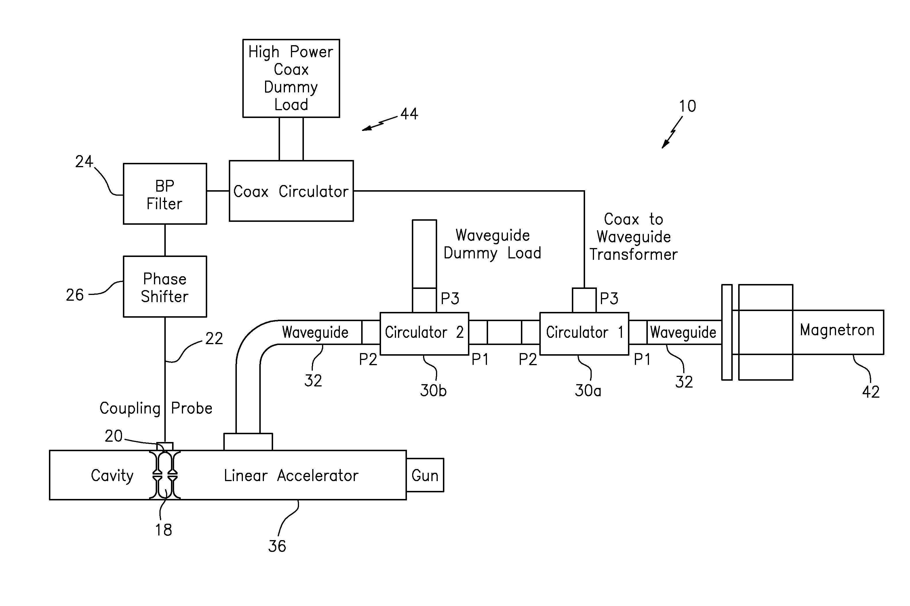
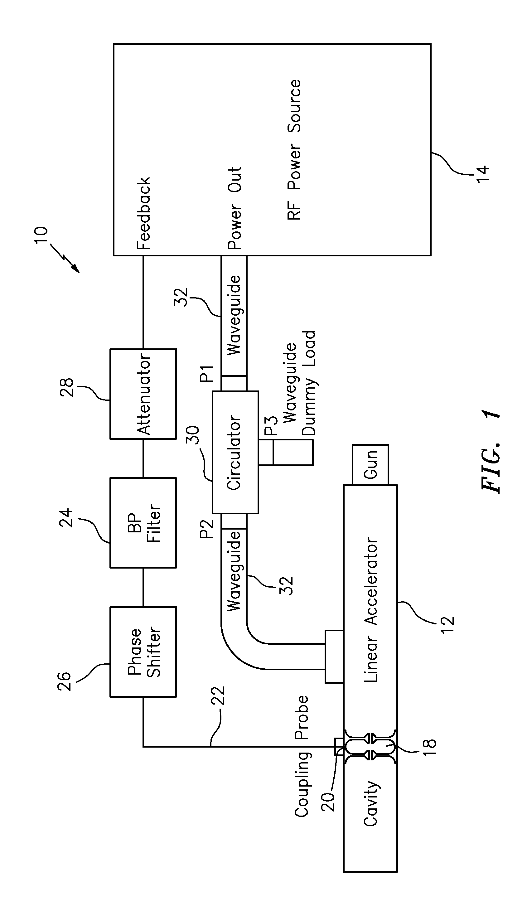
[0092]As previously mentioned, the present invention provides a new frequency control for high power microwave sources, where the accelerator itself functions as the control element. The inventive method and system serve to provide and maintain the required drive frequency to a linear accelerator within a very narrow range.

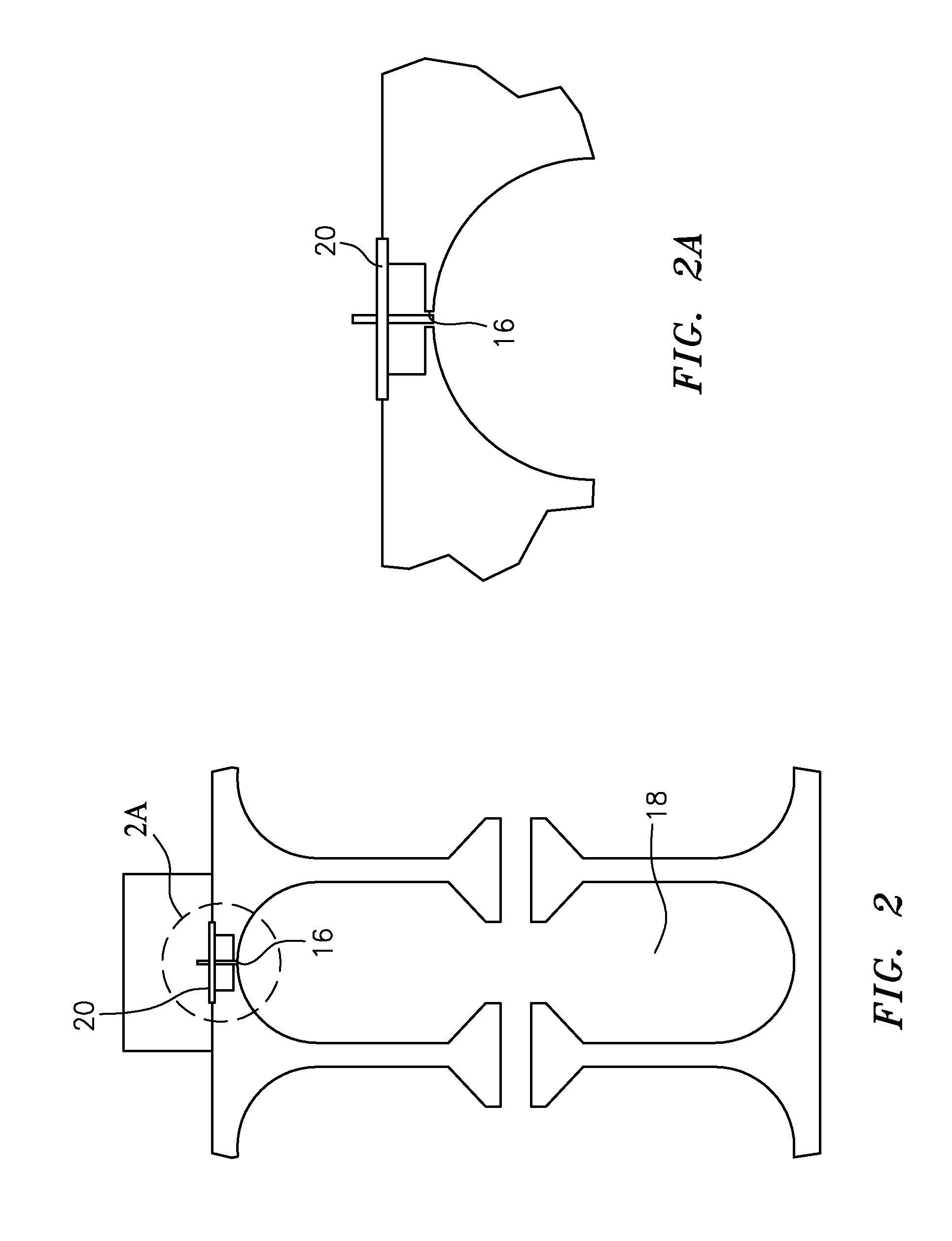
[0093]Referring now to the drawings in detail, an exemplary embodiment of the system of the present invention is shown in FIG. 1, marked with reference numeral 10. In the inventive system 10, a high power linear accelerator 12 is used as a frequency control element for a high power source of microwaves 14. System 10 takes a sample of microwave power from the accelerator 12 and uses this to provide a drive or locking signal for the high power microwave source 14. If the microwave power source 14 is an amplifier such as a klystron or amplitron the signal is used to drive the amplifier. If the microwave power source 14 is a self oscillating tube such as a magnetron t...


PUM


Abstract

A method and system for controlling the frequency of one or more high power microwave sources is provided. The inventive system is made up of a high power linear accelerator, and connected thereto, one or more high power sources of microwaves. In operation, a sample of microwave power from the linear accelerator is used to provide a locking or drive signal for the high power source(s) of microwaves.

Description

RELATED APPLICATION[0001]This application claims priority to U.S. Provisional Patent Application Ser. No. 61 / 663,706, filed Jun. 25, 2012, which is incorporated herein in its entirety by reference.TECHNICAL FIELD[0002]The present invention generally relates to a method and system for controlling the frequency of a high power microwave source, and more particularly relates to a method and system that uses a high power linear accelerator to control the frequency of this microwave source.BACKGROUND AND SUMMARY OF THE INVENTION[0003]High power sources of microwaves such as klystrons and magnetrons serve as the driving force for modern particle accelerators. A klystron is a specialized linear-beam vacuum tube that is used as an amplifier at microwave (and radio) frequencies. As such, the klystron needs an external source of microwaves to drive it. This source must be several hundreds of watts and tunable. Typical klystrons at 3 gigahertz (Ghz) can provide up to 30 megawatts (MW) of peak ...

Claims


Application Information

Patent Timeline
Patent Type & Authority Applications(United States)
IPC IPC(8): H03L7/00
CPCH03L7/00
Inventor LEEK, PAUL H.
Owner LEEK PAUL H
Learn More