
Method and apparatus for diagnosing engine fault

Active Publication Date: 2014-01-09
HONDA MOTOR CO LTD
View PDF12 Cites 7 Cited by
  • Summary
  • Abstract
  • Description
  • Claims
  • Application Information

AI Technical Summary

Benefits of technology

The present invention aims to provide a method and apparatus for diagnosing engine faults quickly and accurately. The method involves judging if a misfire has occurred due to a mechanical fault and identifying which cylinder is suffering from mechanical trouble. This helps to reduce the number of diagnostic man-hours required. Additionally, the method includes stopping the determination of a compression pressure shortage cylinder if certain temperature values are met. This prevents errors in identifying the cylinder.

Problems solved by technology

However, since there are many factors responsible for a misfire, a large amount of time and effort is required to identify the trouble spot.
However, such mechanical inspecting processes require a large expenditure of man-hours for disassembling the engine and adjusting and servicing the engine.
In particular, mechanical causes are problematic in that the process of identifying mechanical causes is highly tedious and time-consuming, since the engine has to be disassembled and serviced.
Thus, it may not be easy to judge whether or not a detected compression pressure is abnormal and requires the engine to be repaired, based simply on the relative difference between instantaneous rotational speeds.

Method used


Image

  • Method and apparatus for diagnosing engine fault
  • Method and apparatus for diagnosing engine fault
  • Method and apparatus for diagnosing engine fault

Examples


embodiment

A. Embodiment

1. Arrangement

(1) Overall Configuration

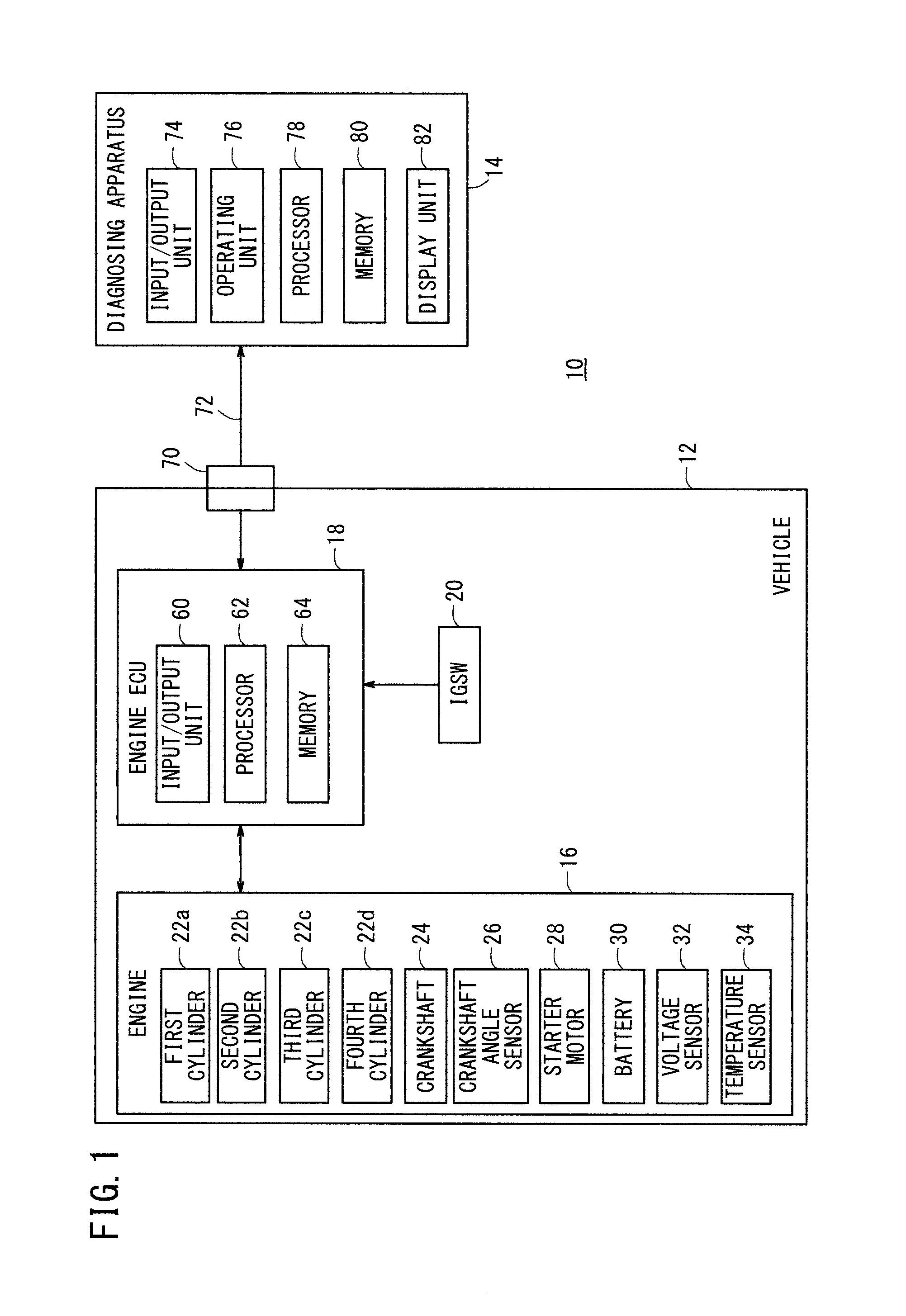
[0056]FIG. 1 is a block diagram showing the general configuration of an engine diagnosing system 10 (hereinafter referred to simply as a “system 10”) having an engine trouble diagnosing apparatus 14 (hereinafter referred to as a “diagnosing apparatus 14”) according to an embodiment of the present invention. The system 10 includes a vehicle 12, which incorporates an engine 16 as an object to be diagnosed, and a diagnosing apparatus 14 for diagnosing the engine 16.

(2) Vehicle 12

(a) Overall Configuration

[0057]The vehicle 12 includes, in addition to the engine 16, an engine electronic control unit 18 (hereinafter referred to as an “engine ECU 18” or an “ECU 18”) for controlling operations of the engine 16, and an ignition switch 20 (hereinafter referred to by “IGSW 20”).

(b) Engine 16

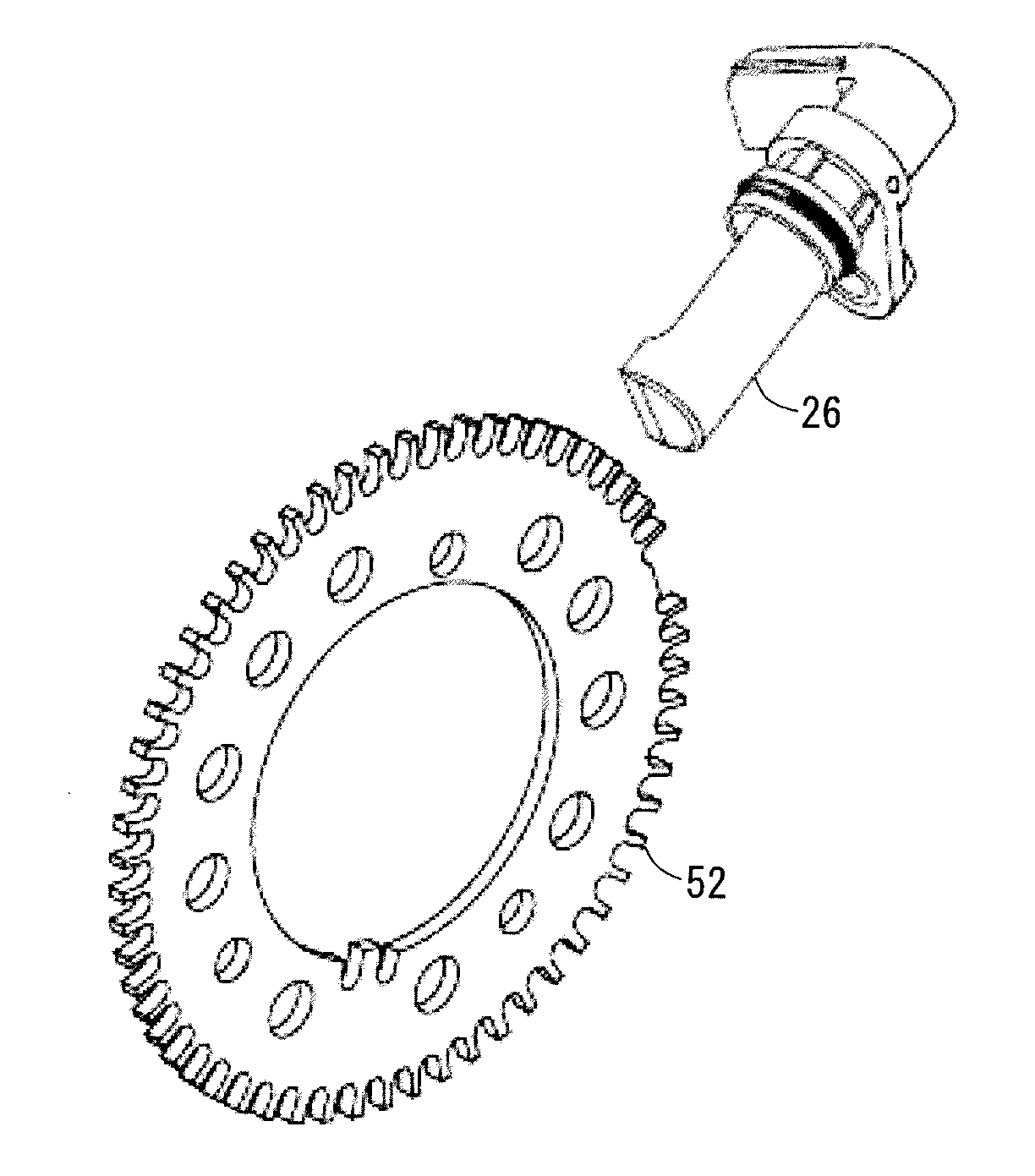
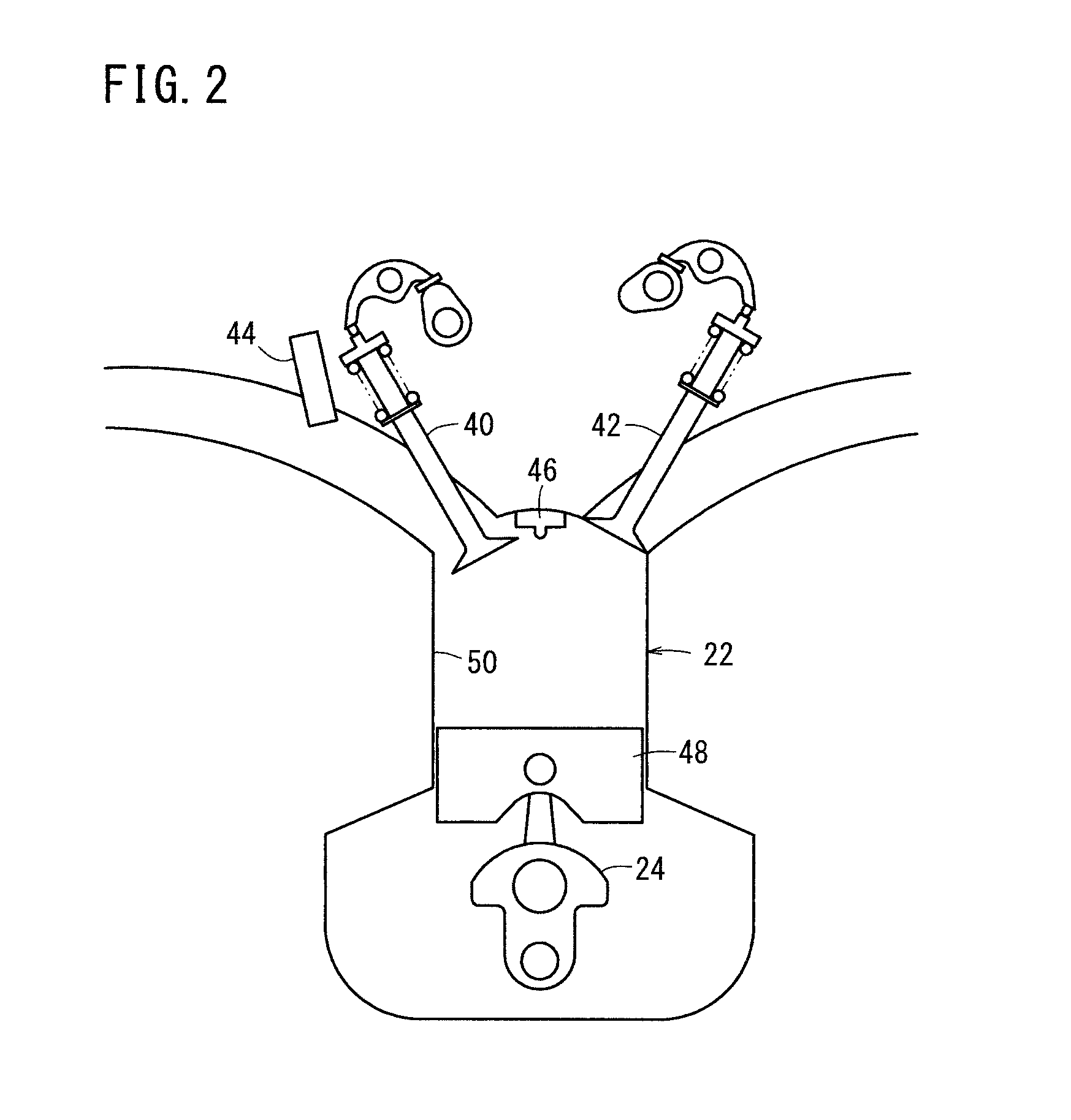
[0058]As shown in FIG. 1, the engine 16 comprises a so-called in-line four-cylinder engine having first through fourth cylinders 22a through 22d (hereinaft...


PUM


Abstract

According to a method and an apparatus of the present invention for diagnosing a fault of an engine, a cranking rotation state is created by rotating a crank shaft while explosions in each cylinder are stopped; a variation of angular velocity of the crank shaft is detected for each cylinder in the cranking rotation state; a cylinder the compression pressure of which is insufficient is detected based on the variation; and if a cylinder indicated as a misfiring cylinder by a fault code is the same as the cylinder detected as being insufficient in compression pressure in the cranking rotation state, the cylinder is specified.

Description

TECHNICAL FIELD [0001]The present invention relates to a method of and an apparatus for diagnosing an engine for a fault, by identifying a misfiring engine cylinder and storing a diagnostic trouble code representative of the misfiring cylinder.BACKGROUND ART [0002]There is known a technology for detecting the occurrence of a misfire in each of cylinders of an engine. See, Japanese Laid-Open Patent Publication No. 2009-280082 (hereinafter referred to as “JP2009-280082A”). According to JP2009-280082A, when a management ECU (117) judges that a misfire has occurred in an internal combustion engine (107), the management ECU turns on a warning lamp (125) (see paragraph [0027]).[0003]There also is known a technology for detecting an abnormal compression pressure in each of cylinders of an engine. See, Japanese Laid-Open Patent Publication No. 2004-019465 (hereinafter referred to as “JP2004-019465A”). According to JP2004-019465A, while a fuel system and an ignition system are inactivated, t...

Claims


Application Information

Patent Timeline
IPC IPC(8): G01M15/11
CPCG01M15/11F02D41/123F02D41/1498F02D41/22F02D2200/021F02D2200/023F02D2200/1015F02D2200/503G01M15/046
Inventor ITO, HIROSHIABE, TAKAYUKIOHNO, TETSUYASHIKAMA, MAHITO
Owner HONDA MOTOR CO LTD
Learn More