
Fan stator structure

Inactive Publication Date: 2014-01-09
ASIA VITAL COMPONENTS SHENZHEN CO LTD
View PDF6 Cites 1 Cited by
  • Summary
  • Abstract
  • Description
  • Claims
  • Application Information

AI Technical Summary

Benefits of technology

The present invention provides a fan stator structure that can change the position of the magnetic force center to reduce noise and wear of the fan and prolong its lifetime. Additionally, the structure enlarges the magnetic conductive area to enhance the operation efficiency of the motor.

Problems solved by technology

When an electronic device operates, high heat is often generated at the same time to affect the working efficiency of the electronic device or even cause crash of the electronic device.
In high-speed operation, the impeller of the fan tends to irregularly shake.
After a long period of shaking and collision, the bearing of the fan is subject to serious wear of the shaft of the impeller.
Under such circumstance, the fan will make mechanical noise in operation and the lifetime of the fan will be shortened.
As a result, the center of magnetic force can be hardly kept in an optimal position.

Method used


Image

  • Fan stator structure
  • Fan stator structure
  • Fan stator structure

Examples


Embodiment Construction

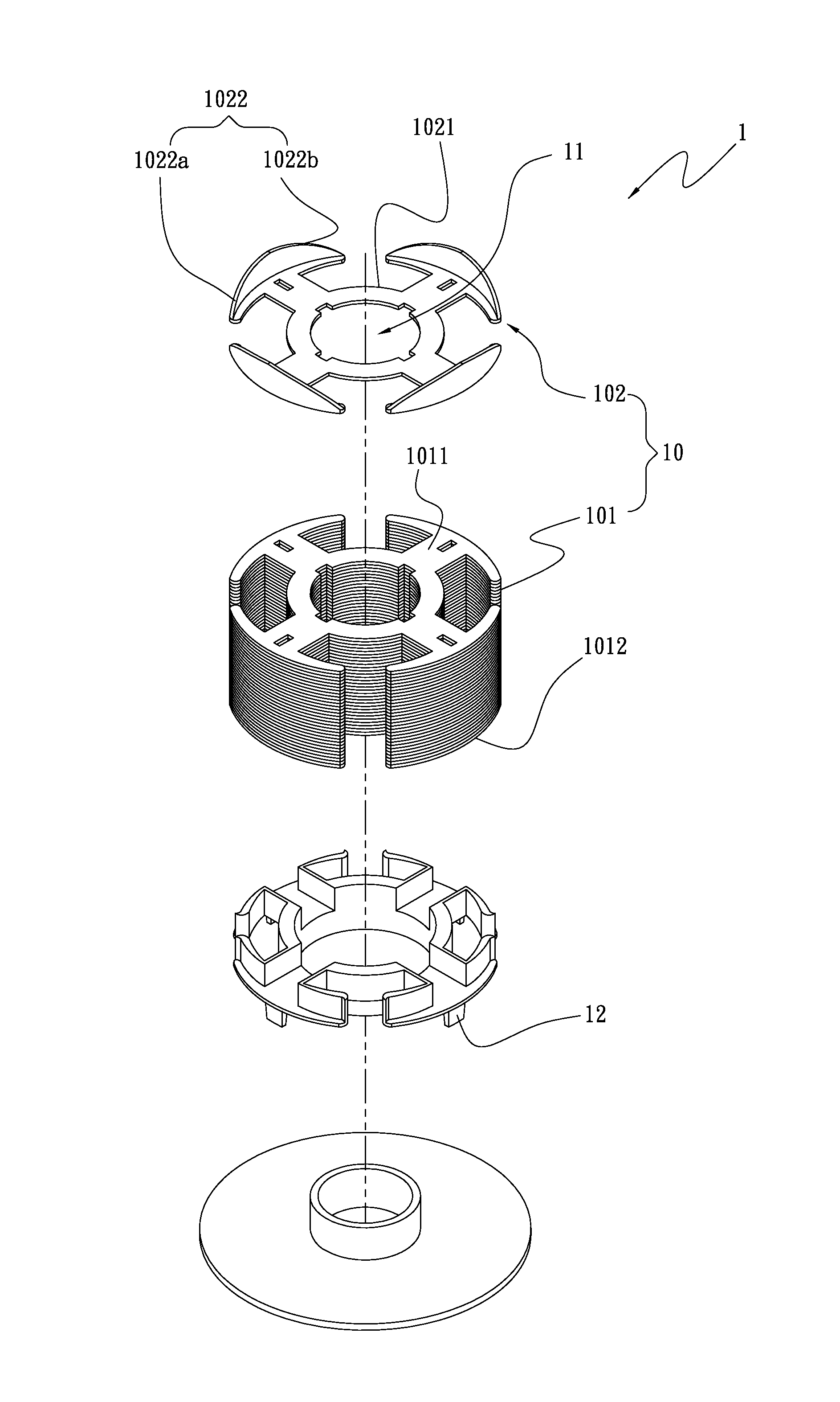
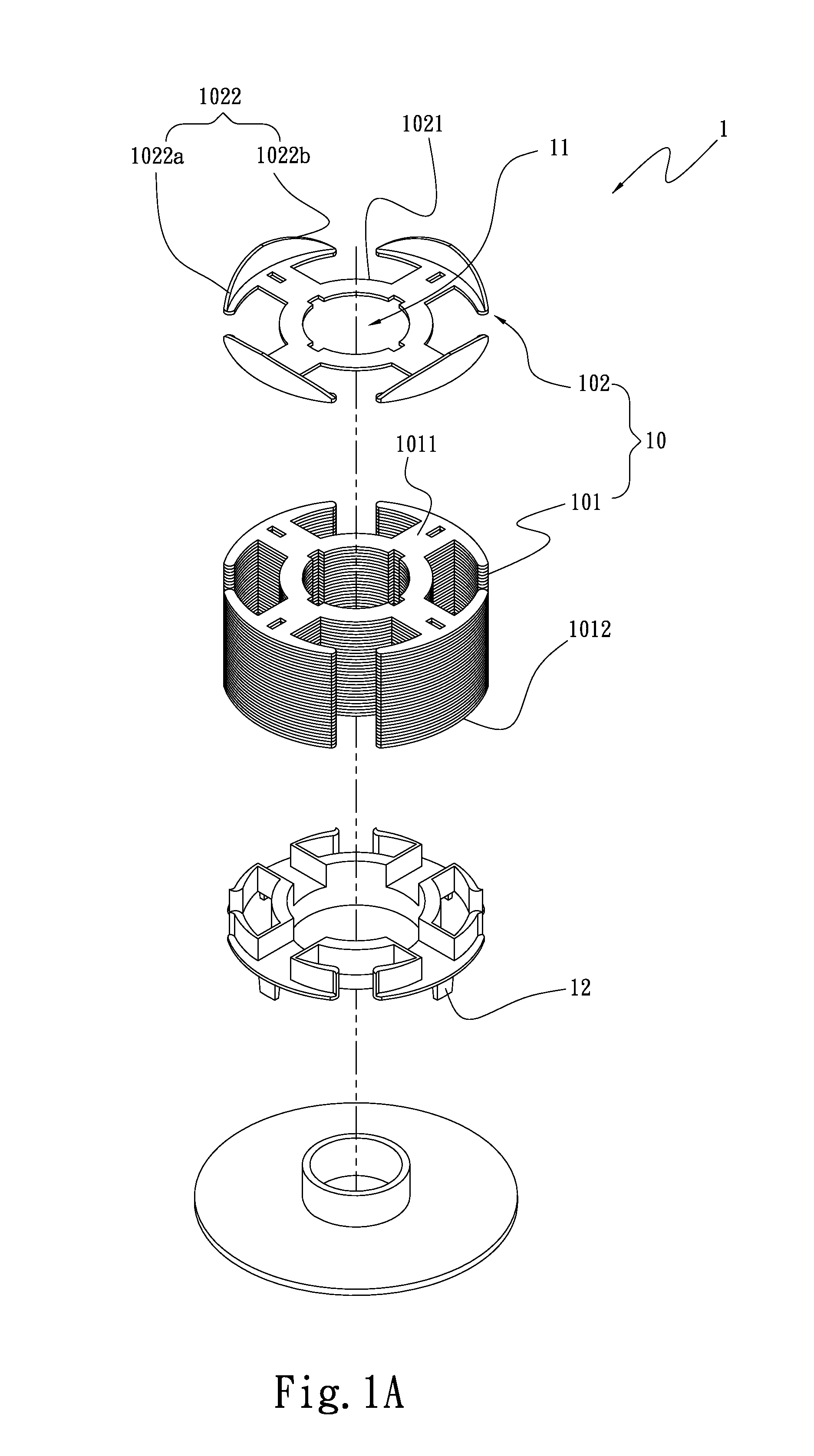
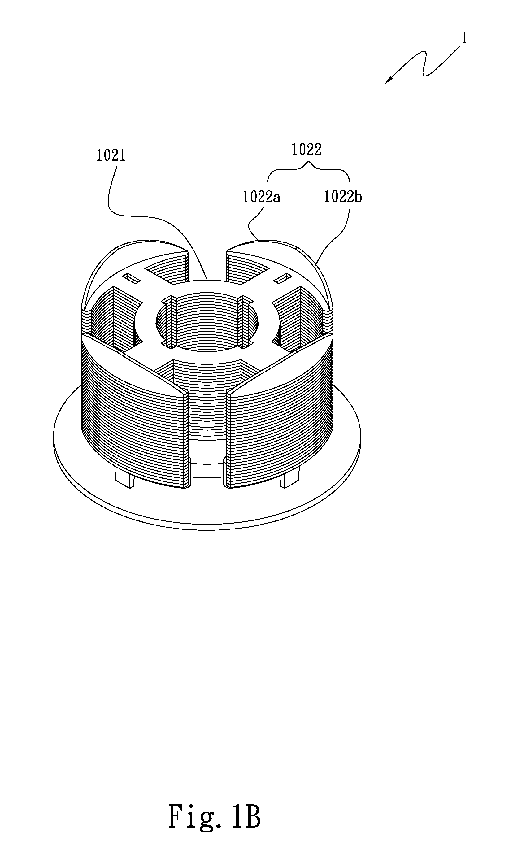
[0027]Please refer to FIGS. 1A and 1B. FIG. 1A is a perspective exploded view a first embodiment of the fan stator structure of the present invention. FIG. 1B is a perspective assembled view the first embodiment of the fan stator structure of the present invention. According to the first embodiment, the fan stator structure 1 of the present invention includes a stator assembly 10 having at least one first silicon steel sheet 101 and at least one second silicon steel sheet 102. The second silicon steel sheet 102 has a base section 1021 and at least one magnetic conductive section 1022. The magnetic conductive section 1022 perpendicularly extends from at least one side of the base section 1021. The first and second silicon steel sheets 101, 102 are stacked to form the stator assembly 10.

[0028]The stator assembly 10 further has a through hole 11 and multiple poles 12. The through hole 11 axially passes through the first and second silicon steel sheets 101, 102. The magnetic conductive ...


PUM


Abstract

A fan stator structure includes a stator assembly having at least one first silicon steel sheet and at least one second silicon steel sheet. The second silicon steel sheet has a base section and at least one magnetic conductive section extending from the base section. The first and second silicon steel sheets are stacked to form the stator assembly. By means of the first and second silicon steel sheets, the position of the magnetic force center of the stator assembly so as to reduce noise and wear ratio and prolong the lifetime of the fan.

Description

BACKGROUND OF THE INVENTION [0001]1. Field of the Invention[0002]The present invention relates generally to a fan stator structure, and more particularly to a fan stator structure, which is able to change the position of the magnetic force center of the stator so as to greatly reduce noise and wear ratio of the fan and prolong the lifetime of the fan.[0003]2. Description of the Related Art[0004]In the modern society, cooling fans with heat dissipation function have become very important components in various electronic products. The cooling fans are applied to many electronic devices ranging from small-size portable electronic devices to large-size electronic equipments of transportation tools. When an electronic device operates, high heat is often generated at the same time to affect the working efficiency of the electronic device or even cause crash of the electronic device. Therefore, the electronic device generally needs a cooling fan to dissipate the heat and lower the temperat...

Claims


Application Information

Patent Timeline
IPC IPC(8): H02K1/16
CPCH02K1/187H02K3/522
Inventor CHOU, CHU-HSIEN
Owner ASIA VITAL COMPONENTS SHENZHEN CO LTD
Learn More