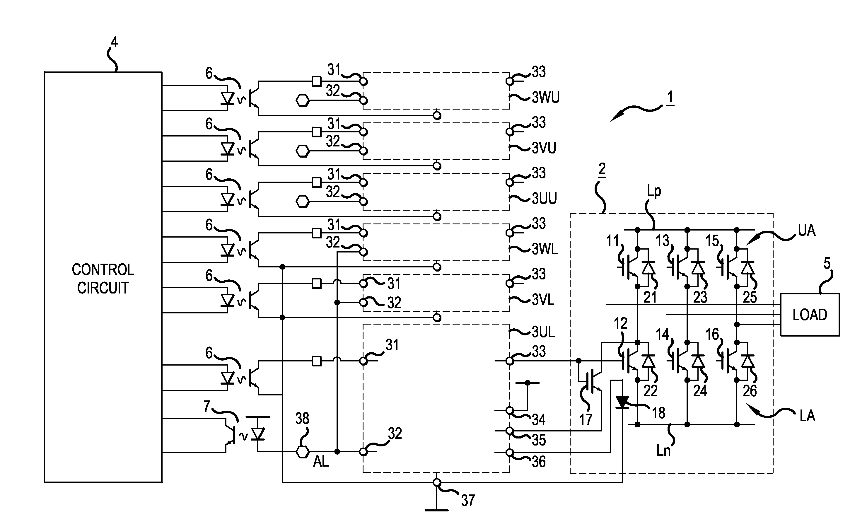
Power conversion device control device
a technology of power conversion device and control device, which is applied in the direction of power conversion system, electronic switching, pulse technique, etc., can solve the problems of increased length of pulse width of error detection signal, increased manufacturing cost, and inability to carry out normal error detection
- Summary
- Abstract
- Description
- Claims
- Application Information
AI Technical Summary
Benefits of technology
Problems solved by technology
Method used
Image
Examples
first embodiment
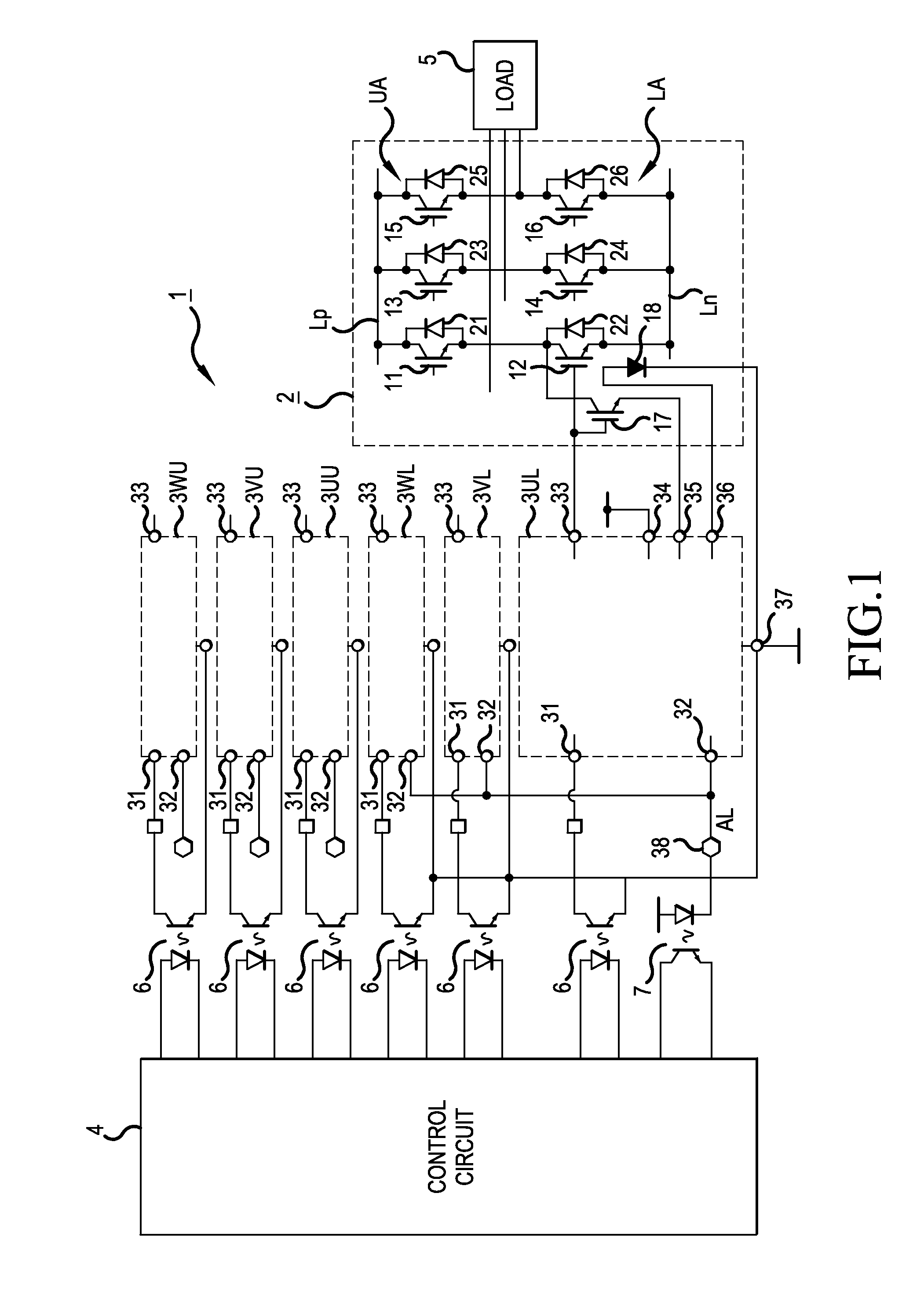
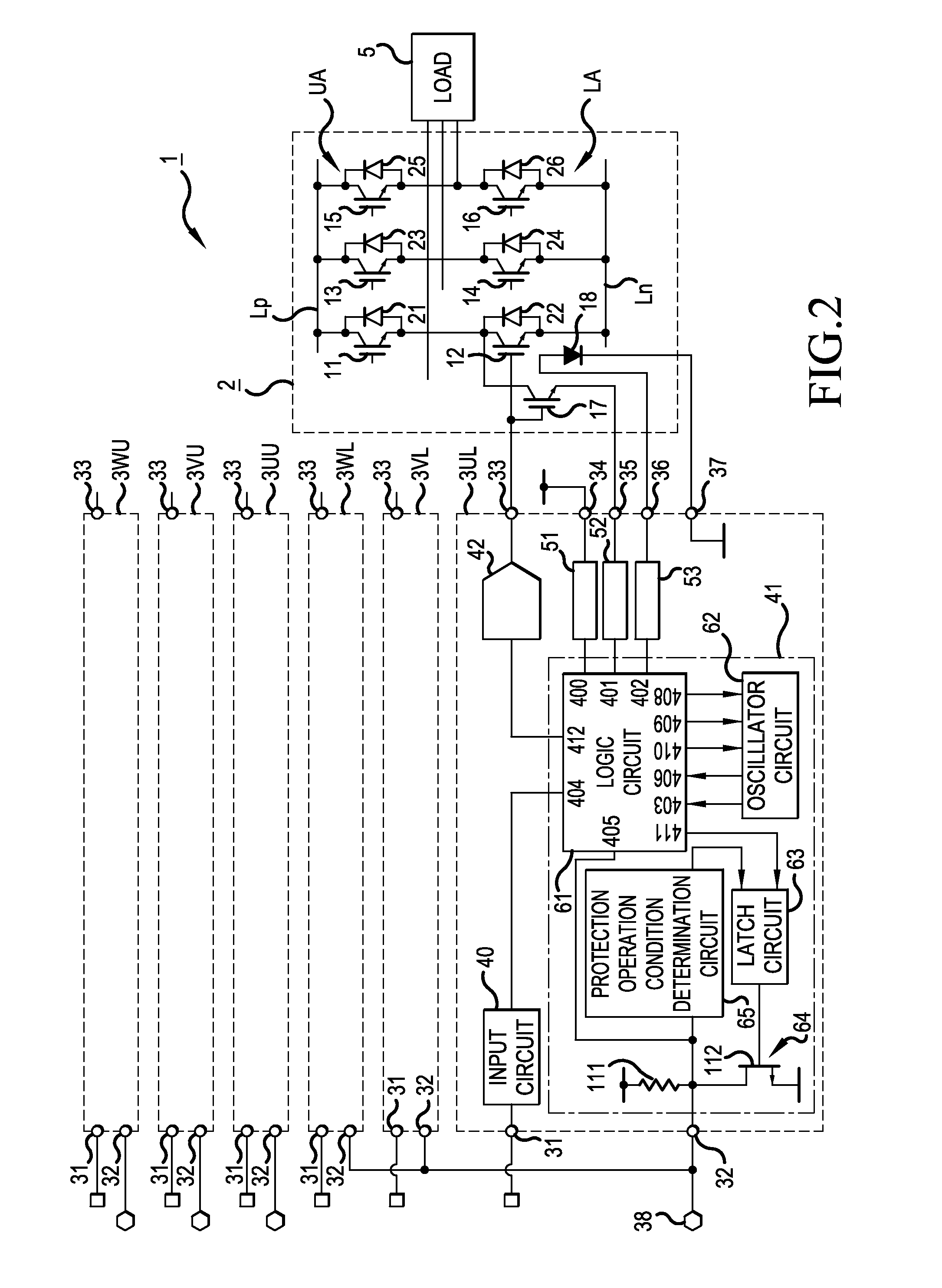
[0093]Next, a description will be given of an operation of the
[0094]Now, it is assumed that the current flowing through the IGBTs 11 to 16 configuring the inverter 2 is below the overcurrent threshold value and normal, that the temperature in the chip in which the IGBTs 11 to 16 are formed is below the overheat threshold value and normal, and furthermore, that the IC power supply voltage supplied to the driver ICs 3UL to 3WL and 3UU to 3WU exceeds the low voltage threshold value and is normal.
[0095]In this normal condition, the protection operation signals H1, H2, and H3 output from the low voltage protection circuit 51, overcurrent protection circuit 52, and overheat protection circuit 53 of the driver ICs 3UL to 3WL and 3UU to 3WU are at a low level. At this time, when all of the RS type flip-flop circuits 416, 426, and 436 and 418, 428, and 438 are in a reset condition in the logic circuit 61, the output of the NOR gate 441 is at a high level. The high level output of the NOR gat...
second embodiment
[0151]Next, a description will be given, referring to FIGS. 10 and 11, of the invention.
[0152]In the second embodiment, instead of the case of setting the determination periods of the pulse signals PS1 to PS3 to differing values, the numbers of pulses are set to differing values.
[0153]That is, in the second embodiment, the oscillator circuit 62 is configured as shown in FIG. 10.
[0154]In the oscillator circuit 62, the determination period signal formation circuits 520 and 540 of the first embodiment are omitted, and the configuration of the determination period signal formation circuit 500 is changed instead.
[0155]That is, as shown in FIG. 10, the determination period signal formation circuit 500 is such that a combination of a series circuit of PMOS-FETs 591 and 592 and a series circuit of PMOS-FETs 593 and 594 is connected in parallel to the PMOS-FETs 505 and 507 configuring a current mirror circuit.
[0156]Also, the gates of the PMOS-FETs 591 and 593 are connected to the gates of th...
PUM
 Abstract
Description
Claims
Application Information
 - R&D
- Intellectual Property
- Life Sciences
- Materials
- Tech Scout
- Unparalleled Data Quality
- Higher Quality Content
- 60% Fewer Hallucinations
Browse by: Latest US Patents, China's latest patents, Technical Efficacy Thesaurus, Application Domain, Technology Topic, Popular Technical Reports.
© 2025 PatSnap. All rights reserved.Legal|Privacy policy|Modern Slavery Act Transparency Statement|Sitemap|About US| Contact US: help@patsnap.com


