Method and apparatus for device to device communication

a communication method and device technology, applied in the field of device to device communication, can solve the problems of network-based solution unreliable, d2d communication at this point in time not being feasible in a lte communication system, and d2d communication in lte systems also encountering difficulties related to proximity detection

Active Publication Date: 2014-01-09
IND TECH RES INST
View PDF8 Cites 88 Cited by
  • Summary
  • Abstract
  • Description
  • Claims
  • Application Information

AI Technical Summary

Benefits of technology

[0016]In order to make the aforementioned features and advantages of the present invention comprehensible, preferred embodiments accompanied with figures are described in detail below. It is to be understood that both the foregoing general description and the following detailed description are exemplary, and are intended to provide further explanation of the invention as claimed.

Problems solved by technology

Therefore, D2D communications at this point in time would not yet feasible in a LTE communication system since the existing LTE's signaling procedures cannot accommodate D2D communications as the most recently published LTE standard, the release 10 (Rel-10), does not include a D2D capability.
In addition to the unavailability of standards or specifications, D2D communication in LTE systems would also encounter difficulties related to the proximity detection.
The network-based solution would then be unreliable as mobile UEs could travel around different cells.
Because of the unreliability of UEs' location information, a network could only provide a list of “potential D2D UEs” for D2D callers, rather than a list of UEs ready to receive D2D connections.
For instance, two UEs may be physically close to each other, but the actual channel status between the two UEs could be poor because of shielding of nearby obstacles.
In this case, two UEs communicating using the D2D connection would not only unfeasible but could be a waste of radio resources.
In any case, network-based solution for UE proximity detection is not only unreliable but is inefficient in view of radio resources.

Method used


Image

  • Method and apparatus for device to device communication
  • Method and apparatus for device to device communication
  • Method and apparatus for device to device communication

Examples


Embodiment Construction

[0041]In this disclosure, 3GPP-like keywords or phrases are used merely as examples to present inventive concepts in accordance with the present disclosure; however, the same concept presented in the disclosure can be applied to any other systems such as IEEE 802.11, IEEE 802.16, WiMAX, and so like by persons of ordinarily skilled in the art.

[0042]A control node in this disclosure would be referred to as a base station (BS) or an eNB. It should be noted that the references of such are merely exemplary and therefore do not serve as limitations to the type of control nodes as it would be apparent to those skilled in the art that other types of control node could be selected to achieve network control purposes such as an advanced base station (ABS), a base transceiver system (BTS), an access point, a home base station, a relay station, a scatterer, a repeater, an intermediate node, an intermediary, and / or satellite-based communication base stations.

[0043]The control node may also be re...


PUM


Abstract

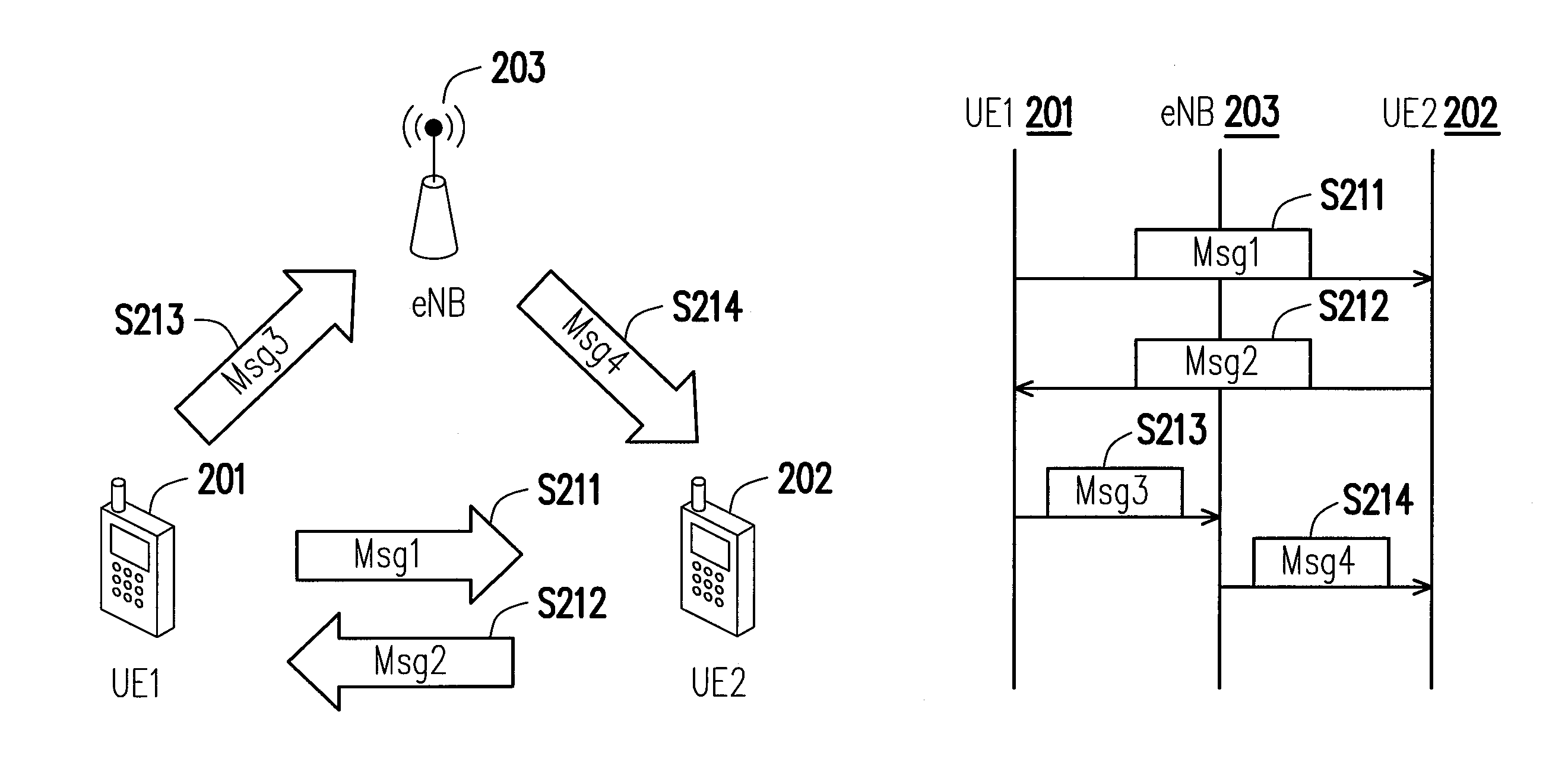
This disclosure proposes a method to achieve D2D (device to device) communication in LTE system. Traditional communication in LTE systems is based on eNB. UEs (User Equipment) need to connect to eNB to send uplink and downlink transmission. Device to device communication is different from the traditional LTE scheme. UEs may directly connect to other UEs, sending data to each other. The disclosure provides the signaling process, based on LTE network entry procedure, to establish D2D communication in LTE system. D2D UEs send Msg1 to another D2D UE, and the recipient respond with Msg2. After the negotiation between D2D UEs, Msg3 and Msg4 are exchanged between UEs and eNB. Several embodiments are provided for the signaling of Msg3 and Msg4. The D2D data transmission may be enabled after the Msg4 or explicit data session initialization.

Description

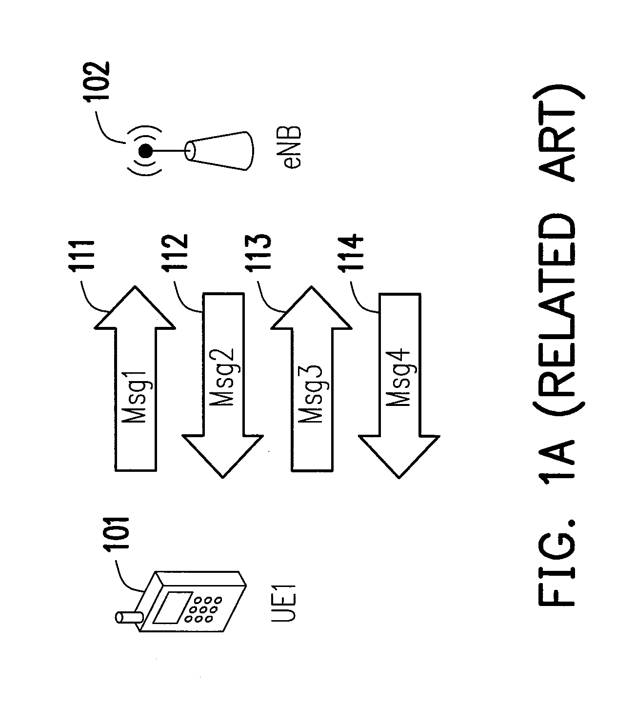
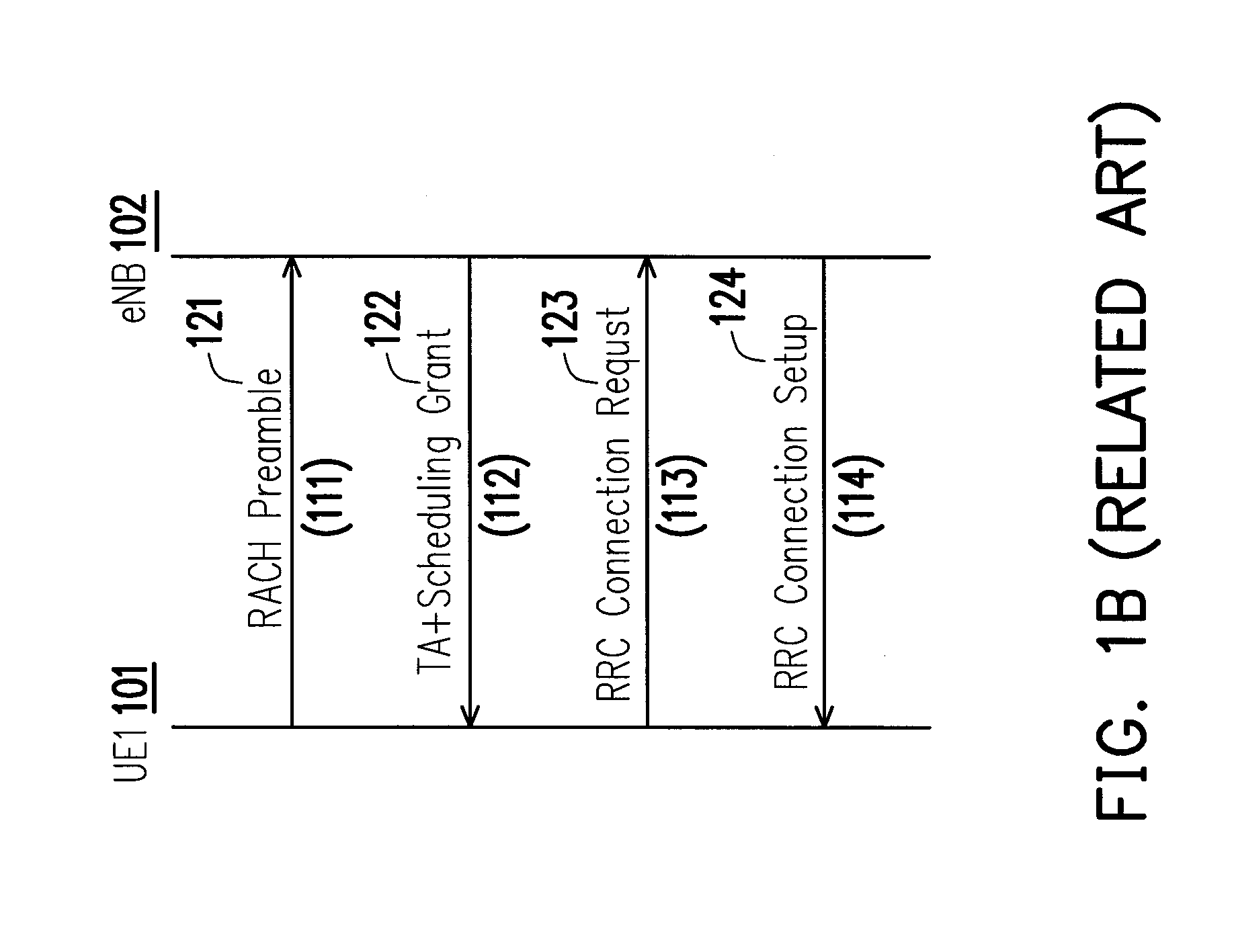
CROSS REFERENCE TO RELATED APPLICATION[0001]This application claims the priority benefit of U.S. provisional application Ser. No. 61 / 669,647, filed on Jul. 9, 2012. The entirety of the above-mentioned patent application is hereby incorporated by reference herein and made a part of this specification.BACKGROUNDTechnical Field[0002]The present disclosure generally relates to a method for device to device (D2D) communications and apparatuses using the same.RELATED ART[0003]Device to Device (D2D) communication is a technology which enables UEs (User Equipment) to communicate with each other without an eNB's (enhanced NodeB or eNodeB) forwarding data in between. A traditional LTE communication system generally requires a UE to first establish a connection with an eNB before it may access the communication system. The operating principle of a traditional LTE communication system could be described using an example as follows. Supposedly that there are two UEs, UE1 and UE2, and both of whi...

Claims


Application Information

Patent Timeline
Patent Type & Authority Applications(United States)
IPC IPC(8): H04W76/02
CPCH04W76/023H04W76/14H04W8/005
Inventor WEI, HUNG-YUCHOU, CHING-CHUN
Owner IND TECH RES INST
Why Eureka
Try Eureka