Radiation generating apparatus and radiation image taking system

a radiation generation apparatus and radiation image technology, applied in the direction of instruments, radiation beam directing means, nuclear engineering, etc., can solve the problem that the heel effect may not effectively reduce the shading, and achieve the effect of increasing the size of the apparatus and reducing shading

Inactive Publication Date: 2014-01-09
CANON KK
View PDF12 Cites 5 Cited by
  • Summary
  • Abstract
  • Description
  • Claims
  • Application Information

AI Technical Summary

Benefits of technology

[0015]Accordingly, it is an object of the present invention to reduce shading in a light projecting / sighting device of a radiation generating apparatus without increasing the size of the apparatus.

Problems solved by technology

Further, even when the radiation tube 103 is a reflection type radiation tube, depending on the angle at which the reflection mirror 105 is provided, the heel effect may not effectively reduce the shading.

Method used


Image

  • Radiation generating apparatus and radiation image taking system
  • Radiation generating apparatus and radiation image taking system
  • Radiation generating apparatus and radiation image taking system

Examples


example 1

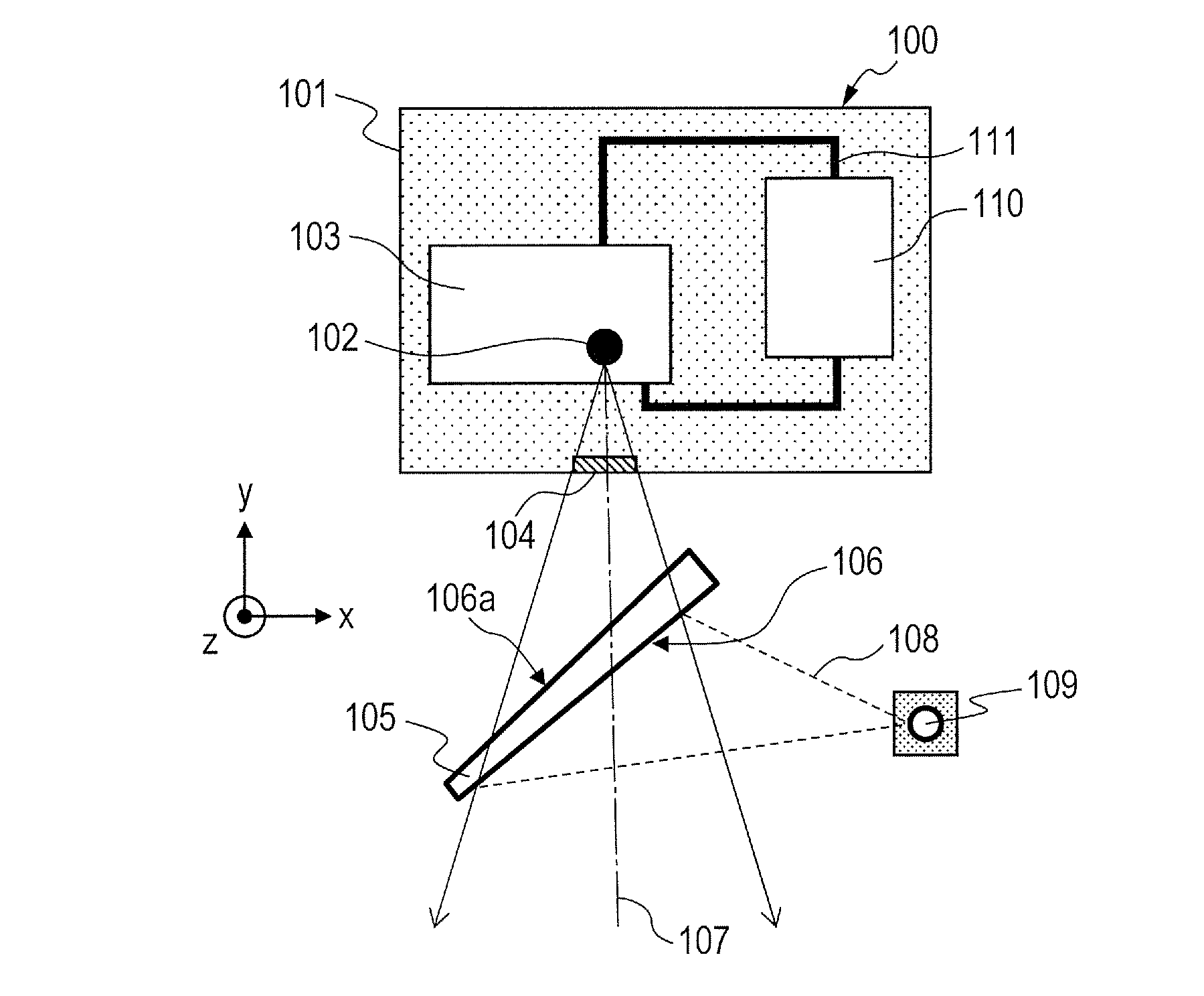
[0069]The radiation generating apparatus configured as illustrated in FIGS. 1 and 5B was manufactured.

[0070]The size of the transmission window 104 was set so that radiation emitted from the focal point 102 had a spread of θ=15° at the maximum with respect to the central axis 107. The reflection mirror 105 included a base material layer which was an acrylic board and a reflective material layer which was a film formed by vapor depositing aluminum, and was provided so that the normal to the reflection plane 106 and the central axis 107 formed an angle φ of 45°. Further, the base material layer had variation in thickness so that the transmission length “a” of radiation which passed through the reflection mirror 105 was about 3 mm.

[0071]In this example, the thickness of the portion of the base material layer through which radiation emitted along the central axis 107 passed was 2.05 mm. Further, the thickness of the portion of the base material layer on the side which was close to the f...

example 2

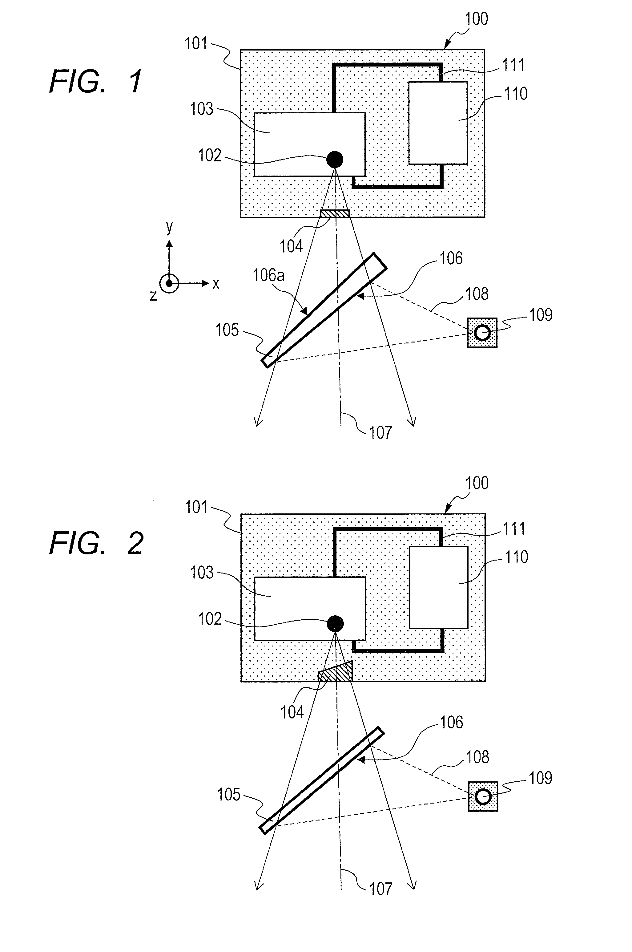
[0072]The radiation generating apparatus configured as illustrated in FIG. 2 was manufactured.

[0073]The reflection mirror 105 included a base material layer which was an acrylic board having a uniform thickness and a reflective material layer which was formed by vapor depositing aluminum. Further, the transmission window 104 was provided in the shape of a wedge in section so that the side thereof on which the focal point 102 and the reflection mirror 105 were close to each other was at a thickness of 4 mm and the side thereof on which the focal point 102 and the reflection mirror 105 were distant from each other was at a thickness of 3 mm. Portions other than that were similar to those in Example 1. It was possible to obtain an effect equivalent to that in Example 1 using the standard reflection mirror 105.

example 3

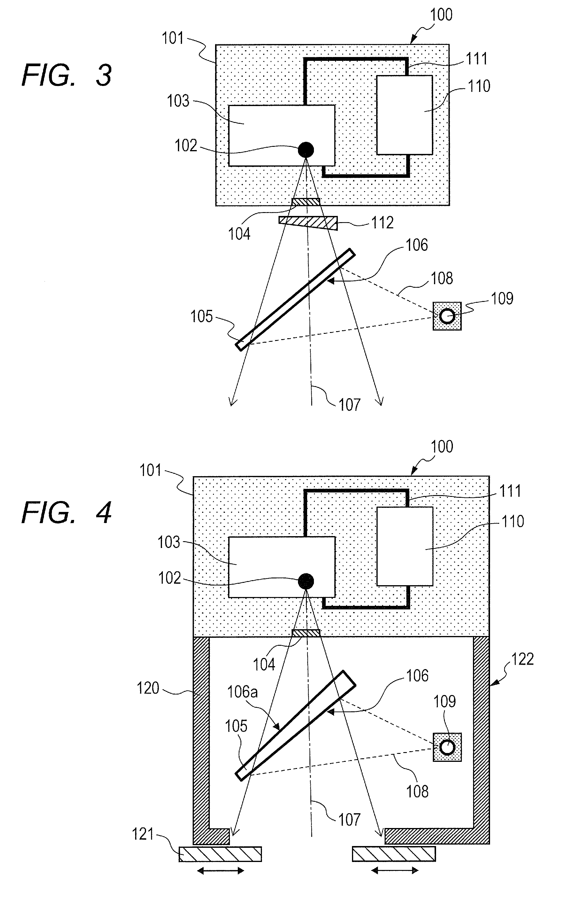
[0074]The radiation generating apparatus configured as illustrated in FIG. 3 was manufactured.

[0075]The reflection mirror 105 included a base material layer which was an acrylic board having a uniform thickness and a reflective material layer which was formed by vapor depositing aluminum. Further, the filter plate 112 made of aluminum in the shape of a wedge in section was provided in an intermediate portion between the reflection mirror 105 and the transmission window 104 so that the side thereof on which the focal point 102 and the reflection mirror 105 were close to each other was at a thickness of 2 mm and the side thereof on which the focal point 102 and the reflection mirror 105 were distant from each other was at a thickness of 1 mm. Portions other than that were similar to those in Example 1.

[0076]It was possible to obtain an effect equivalent to that in Example 1, and in addition, it was possible to block unnecessary radiation by the filter plate 112.

[0077]In the radiation ...


PUM


Abstract

Provided is a radiation generating apparatus, including a radiation generating unit for emitting radiation through a transmission window, and a light projecting/sighting device including a light source for emitting visible light and a reflection mirror. At least one of the transmission window and the reflection mirror has variations in thickness for reducing shading of radiation which irradiates a radiation irradiation field.

Description

BACKGROUND OF THE INVENTION[0001]1. Field of the Invention[0002]The present invention relates to a radiation generating apparatus including a light projecting and sighting device (hereinafter, referred to as “light projecting / sighting device”) and a radiation image taking system using the radiation generating apparatus.[0003]2. Description of the Related Art[0004]A radiation generating apparatus includes a light projecting / sighting device for irradiating, with visible light, a region coincident with a radiation irradiation field so that the radiation irradiation field can be visually recognized. The light projecting / sighting device irradiates a subject with visible light emitted from a visible light source and reflected by a reflection mirror. Generally, the reflection mirror is provided so as to cover the irradiation path of radiation, and reflects visible light and transmits radiation.[0005]It is known to, by causing the reflection mirror to be movable and retracting the reflectio...

Claims


Application Information

Patent Timeline
Patent Type & Authority Applications(United States)
IPC IPC(8): G21K1/00G21K1/10
CPCG21K1/00G21K1/10A61B6/08H01J35/18H01J35/116H01J35/186H01J35/16H01J2235/18H05G1/02
Inventor TSUJINO, KAZUYA
Owner CANON KK
Why Eureka
Try Eureka