
Hand-Held Dual-Magnification Dermatoscope

a dermatoscope and magnification technology, applied in the field of dermatoscopes, can solve the problems of wasting space, obscuring the light that penetrates through the skin and reflecting off the aberration being examined, and taking a considerable longer time to use, so as to increase the viewable skin, the effect of wasting spa

Inactive Publication Date: 2014-01-09
ROSEN ROBERT
View PDF20 Cites 4 Cited by
  • Summary
  • Abstract
  • Description
  • Claims
  • Application Information

AI Technical Summary

Benefits of technology

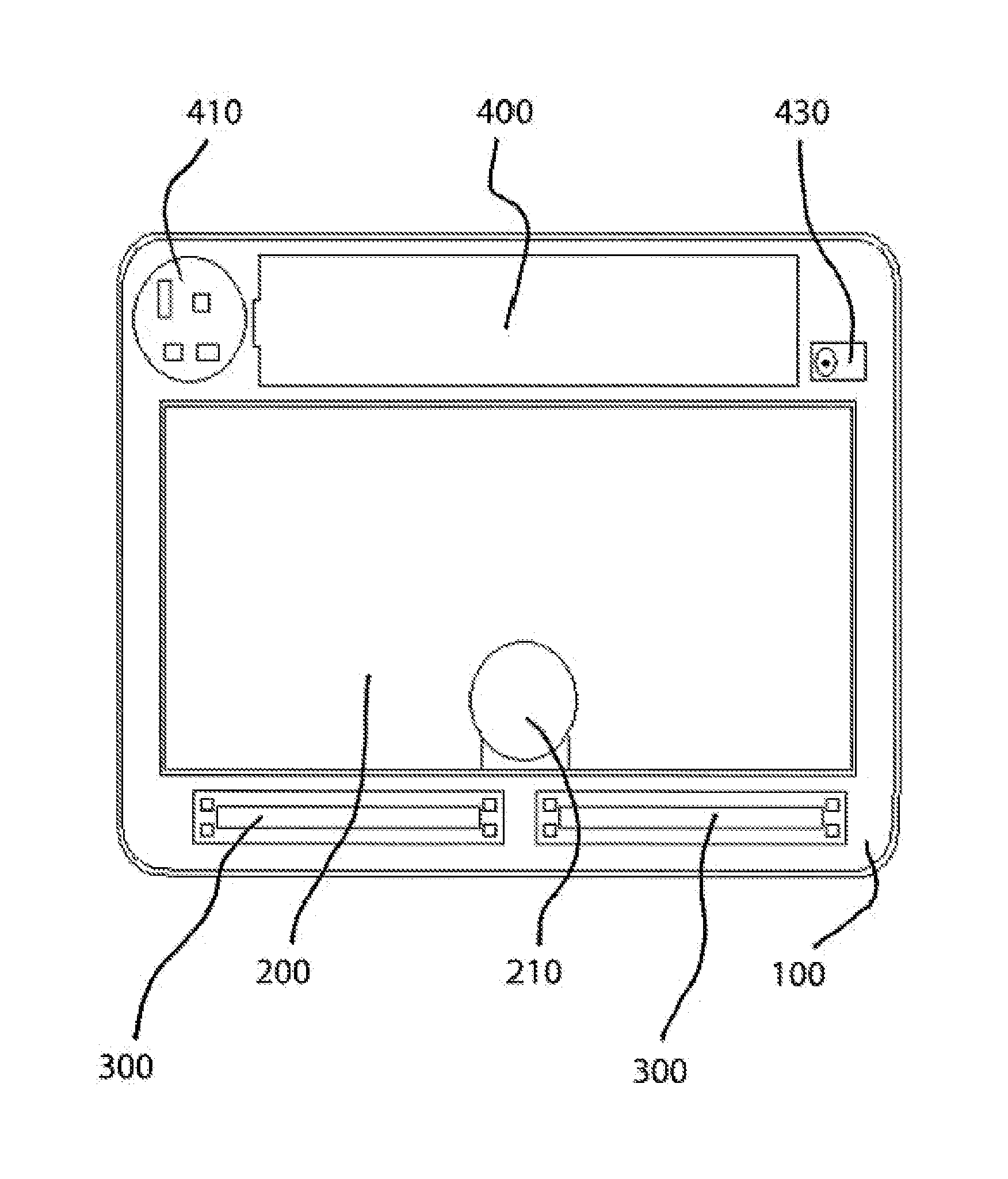
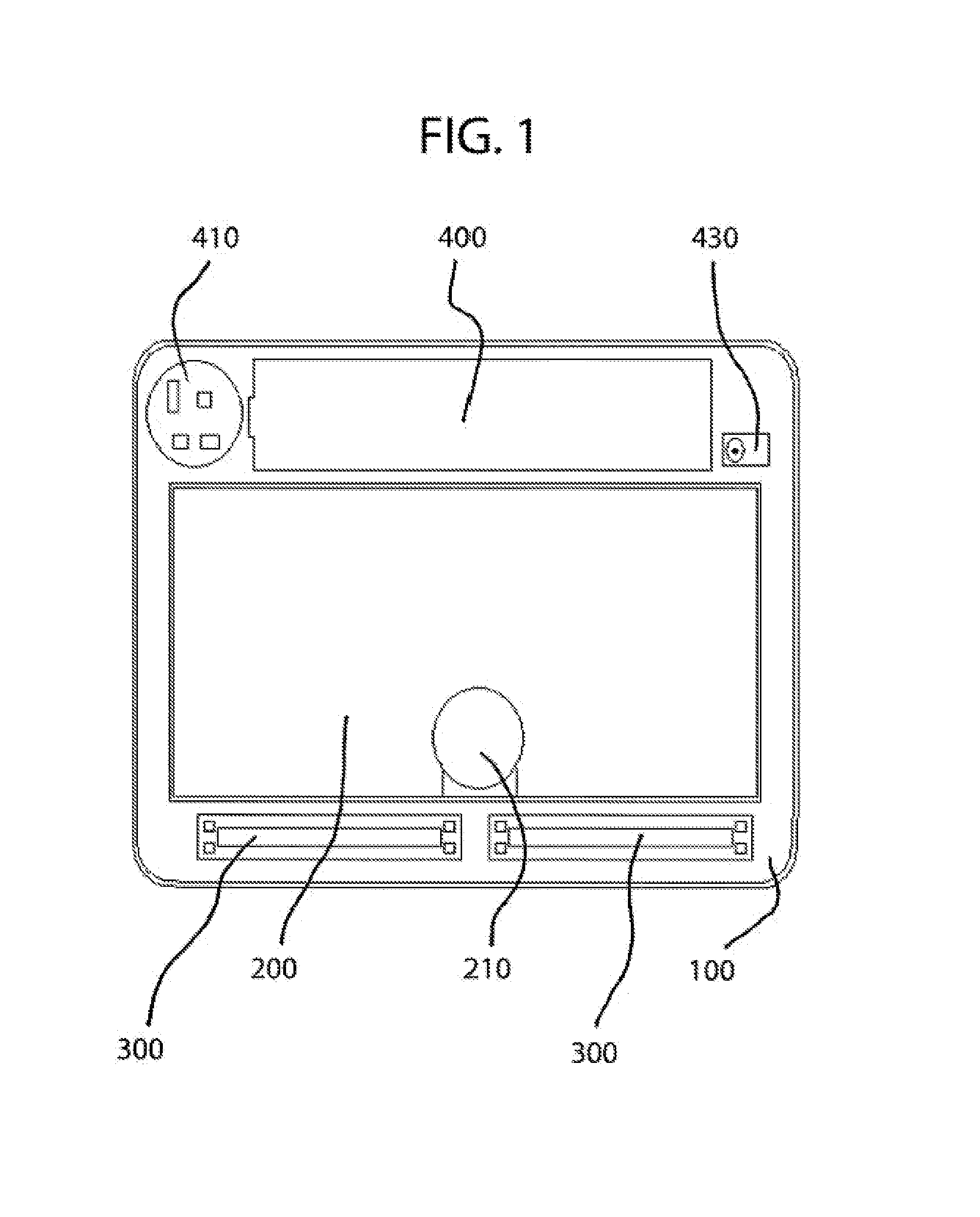
The present invention provides a single unit magnifier comprising two magnifiers, a large one at 2×magnification and a small one at 10×magnification. This results in a smaller magnifier but has a greater field of view because the eye naturally moves from side to side, not vertically. This avoids having considerable waste of space in the vertical dimension for circular lenses. The device is lit by a chip-on-board light-emitting diode and a thin polarizing filter covers both lenses to eliminate glare from light that reflects off the surface of the skin. The device is portable, uses a rechargeable lithium iron phosphate battery, and a physician can use it to quickly examine a patient's skin using the lower-powered magnifier and then perform a more thorough examination using the high-powered magnifier without the risk of not finding the aberration when exchanging dermatoscopes.

Problems solved by technology

It is a hand-held device, but is much larger than can fit in one's pocket, and has significant weight that fatigues a doctor using it for long periods of time.
In practice, dermatologists seldom use the parallel-polarization feature, which allows too much light reflected from the skin's surface to transmit through the lens, thereby obscuring the light that penetrates through the skin and reflects off the aberration being examined.
This device is useful for conducting a more detailed examination of the a mole or other skin aberration than the Lumio, but takes considerably longer time to use.
When using these devices, a dermatologist would have to switch between the devices once the cursory screening using the Lumio showed an aberration of interest.
This slows down the examination, and is inconvenient for the doctor.

Method used


Image

  • Hand-Held Dual-Magnification Dermatoscope
  • Hand-Held Dual-Magnification Dermatoscope
  • Hand-Held Dual-Magnification Dermatoscope

Examples


Embodiment Construction

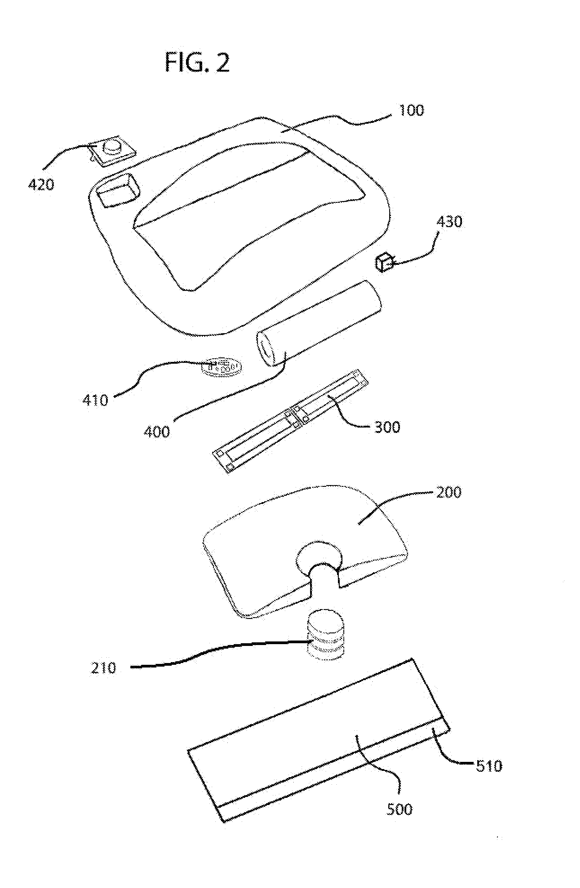
[0021]The drawings are for illustrative purposes of the preferred embodiment of the present invention. FIGS. 1 and 2 show the various components of the preferred embodiment. Top housing 100 comprises the housing for the invention, into which the various components are placed. It is preferably made of plastic.

[0022]The dermatoscope is powered by battery 400, which is preferably a rechargeable lithium iron phosphate battery (LiFePO4). This battery has the advantage of storing considerable electrical charge at 3 amps at about 3.3 volts, yet is very stable, unlike standard lithium batteries than can catch fire when mishandled or damaged. The cost and complexity of the product is greatly reduced by avoiding such circuitry, such as that found in cell phones.

[0023]Charging jack 430 is a standard charging jack that interrupts switching circuit 410's connection to battery 400 to enable recharging. Charging jack 430 is well known to those in the art.

[0024]Opposite battery 400 is a wall on whi...


PUM


Abstract

A one-piece hand-held dermatoscope have two magnifier lenses, a larger rectangular-shaped lens between two and three times magnification power, and a smaller circular lens between eight and 15 times magnification power. A polarizer is position between the lens and a patient's skin. In one embodiment, the polarizer is radial, such that cross-polarization is achieved when the light reflect off the skin and passes through it a second time. In another embodiment, the portion of the polarizer through which the light passes to the skin is linear in a first direction, and the portion through which the light passes back from the skin is linear in a second direction that is perpendicular to the first direction, enabling cross-polarization.

Description

CROSS-REFERENCE TO RELATED APPLICATIONS[0001]Not ApplicableSTATEMENT REGARDING FEDERALLY SPONSORED RESEARCH OR DEVELOPMENT[0002]Not ApplicableTHE NAMES OF THE PARTIES TO A JOINT RESEARCH AGREEMENT[0003]Not ApplicableINCORPORATION-BY-REFERENCE OF MATERIAL SUBMITTED ON A COMPACT DISC[0004]Not ApplicableBACKGROUND OF THE INVENTION[0005]1. Field of the Invention[0006]This invention relates generally to the field of dermatoscopes, and more particularly to a pocket-sized dermatoscope with two different magnification lenses, each having cross-polarization.[0007]2. Background Art[0008]Dermatoscopy (also known as dermoscopy or epiluminescence microscopy) refers to the use of a dermatoscope to examine the skin for aberrations or disease. Dermatoscopes were originally placed in contact with the skin through a glass plate moistened with oil or other liquid to eliminate reflections from the outer skin surface. A new generation of dermatoscopes that do not require skin contact were developed by 3...

Claims


Application Information

Patent Timeline
IPC IPC(8): A61B6/00
CPCA61B5/0077A61B5/441
Inventor ROSEN, ROBERT
Owner ROSEN ROBERT
Learn More