Robot

a robot and robot technology, applied in the field of robots, can solve the problems of air leakage outside, damage to the cable, and upsizing of the joint structure, and achieve the effect of preventing damage to the cabl

Active Publication Date: 2014-01-16
CANON KK
View PDF16 Cites 32 Cited by
  • Summary
  • Abstract
  • Description
  • Claims
  • Application Information

AI Technical Summary

Benefits of technology

[0012]In view of this, the present invention has an object to provide a robot

Problems solved by technology

At this time, the cable may sag to repeatedly collide with and slide on a peripheral device, and thus the cable may be damaged.
In particular, when the cable is air piping, the cable may bend at a small curvature radius to fluctuate the air pressure, or air may leak outside from a flaw generated in the cable.
However, in order to enable cable twisting, it is necessary to provide the cable three-dimensionally in a rotational axis direction, which leads to a problem in that the joint structure is upsized.
However, when the cable is laid along the side surface of each frame, the cable may be bent by the bending movement about the joint axis, which may cause flexure of the cable in the joint axis direction.
To address this problem, there is a me

Method used


Image

  • Robot
  • Robot
  • Robot

Examples


first embodiment

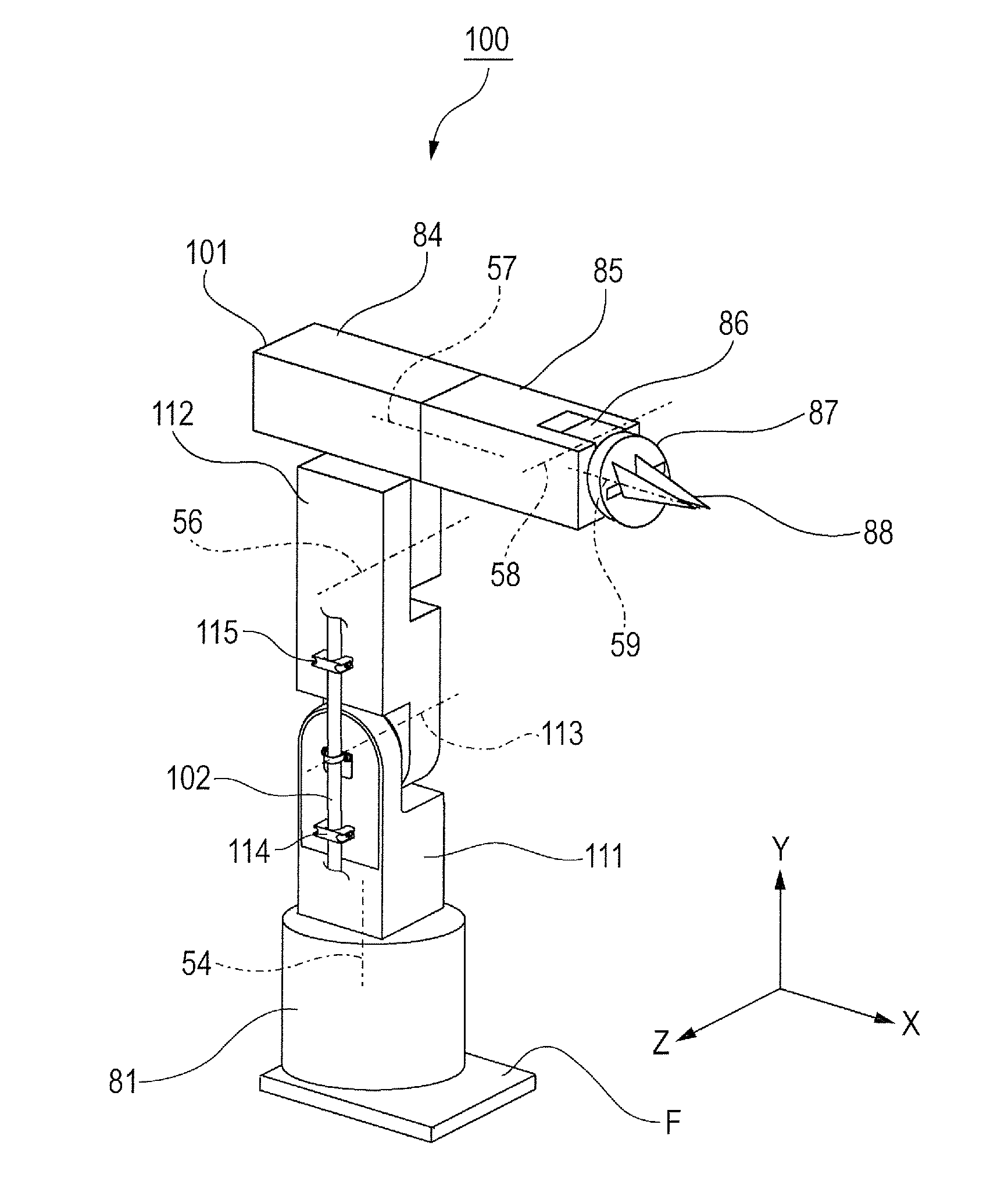
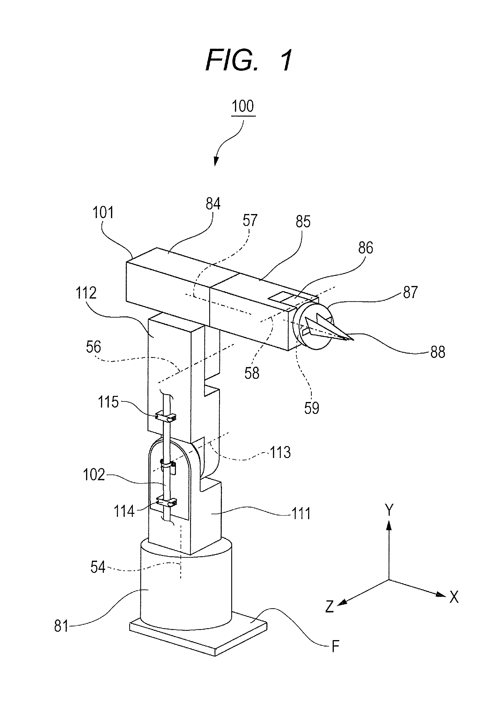
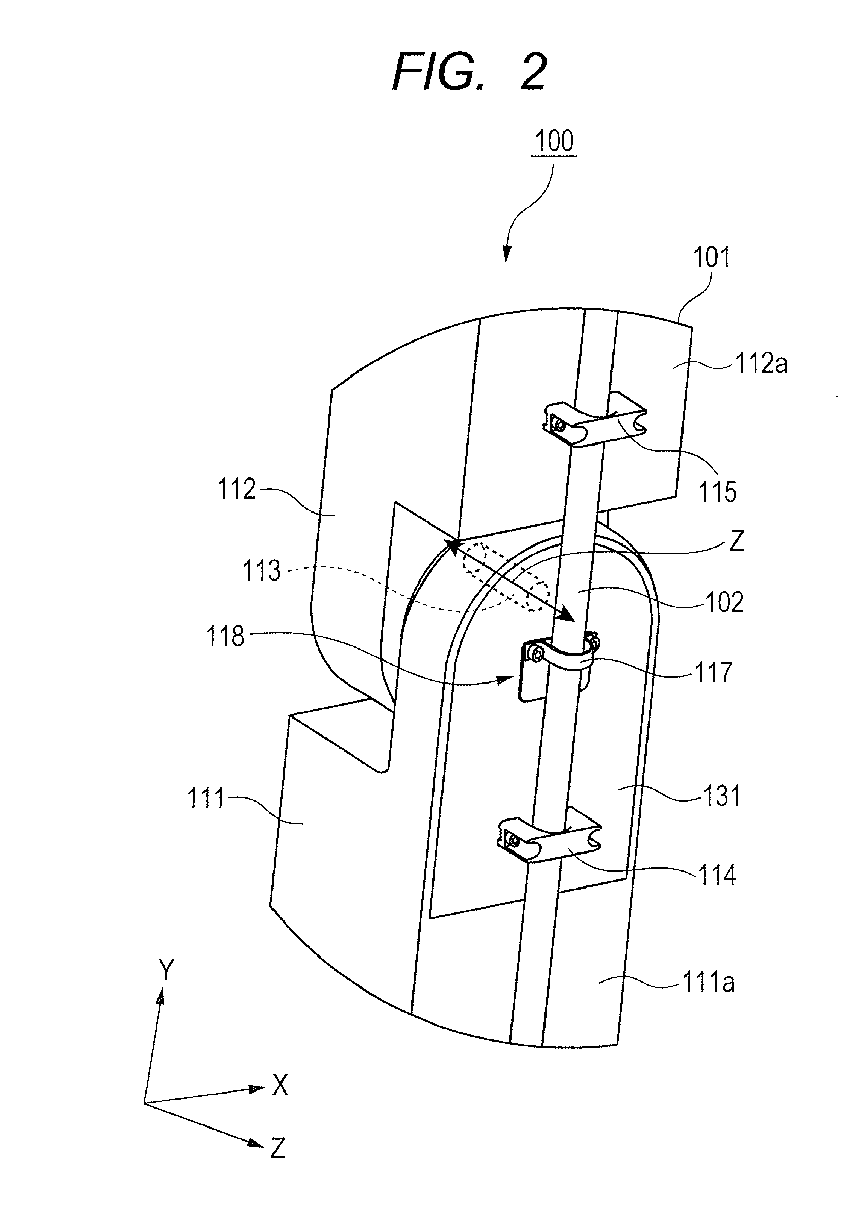
[0033]FIG. 1 is a perspective view illustrating a schematic configuration of a robot according to a first embodiment of the present invention. Note that, in FIG. 1, the front-right direction of the drawing sheet is referred to as an X direction, the front-left direction of the drawing sheet is referred to as a Z direction, and an upward direction of the drawing sheet is referred to as a Y direction. Further, FIG. 2 is a partial perspective view illustrating the schematic configuration of the robot according to the first embodiment of the present invention. A robot 100 illustrated in FIG. 1 is an industrial robot, and includes a 6-axis robot arm 101, an end effector (for example, robot hand) 88 provided on a distal end of the robot arm 101, and a cable 102 laid along the outer side surface of the robot arm 101.

[0034]The robot arm 101 includes a frame 111 serving as a first frame (first link) formed of a longitudinal member, and a frame 112 serving as a second frame (second link) form...

second embodiment

[0071]Next, a robot according to a second embodiment of the present invention is described. FIG. 10 is a perspective view illustrating a holding member and a support mechanism of the robot according to the second embodiment of the present invention. Note that, the configuration of the robot arm is similar to that in the first embodiment, and hence the robot arm is described with reference to FIG. 1.

[0072]In FIG. 10, a support mechanism 218 includes a rocking plate 229 serving as a first rocking member supported by the side surface 111a (FIG. 1) of the frame 111 serving as the first frame so as to be rockable about an axis C21 serving as a first axis of a rotating shaft 228 provided in parallel to the joint shaft 113 (FIG. 1). The support mechanism 218 further includes a rocking plate 230 serving as a second rocking member supported by the rocking plate 229 so as to be rockable about an axis C22 of a rotating shaft 231 as a second axis provided differently from the axis C21 and in pa...

third embodiment

[0079]Next, a robot according to a third embodiment of the present invention is described. In the first embodiment, the state in which the longitudinal axis of the frame 112 is provided in parallel to that of the frame 111 is referred to as the reference posture, and the case where turning is performed symmetrically from the reference posture is described. However, in a general industrial robot, from the reason of the movable region of the robot arm 101, there are many cases where the frame 112 does not move symmetrically with respect to the reference posture about the joint. In the third embodiment, the case where the frame 112 does not move symmetrically about the joint is described.

[0080]FIGS. 11A and 11B are schematic views illustrating a robot 300 according to the third embodiment of the present invention. In this robot arm 101, when the frame 112 turns on the right and left sides from the reference state in which the longitudinal axis of the frame 111 and the longitudinal axis...


PUM


Abstract

A robot, includes: a robot arm including: a first frame; and a second frame coupled to the first frame to be turnable about a joint axis; a cable arranged along a side surface of the first frame and a side surface of the second frame; a first fixing member for fixing the cable to the side surface of the first frame; a second fixing member for fixing the cable to the side surface of the second frame; a holding member for holding a part of the cable between the first fixing member and the second fixing member; and a support mechanism for regulating movement of the holding member in an axis direction of the joint axis, the support mechanism supporting the holding member so that the holding member is movable in a direction orthogonal to the axis direction of the joint axis to follow a bending movement of the cable.

Description

BACKGROUND OF THE INVENTION[0001]1. Field of the Invention[0002]The present invention relates to a robot that includes a robot arm including a first frame and a second frame that are coupled to each other so as to be turnable about a joint axis, and a cable fixed to the robot arm while being laid along a side surface of the robot arm.[0003]2. Description of the Related Art[0004]In a joint portion of an industrial robot, a cable such as a power line, a signal line, and air piping is provided. Along with the rotation of the joint portion, the cable receives bending and twisting forces to be deformed. At this time, the cable may sag to repeatedly collide with and slide on a peripheral device, and thus the cable may be damaged. In particular, when the cable is air piping, the cable may bend at a small curvature radius to fluctuate the air pressure, or air may leak outside from a flaw generated in the cable.[0005]In the joint portion of the industrial robot, the cable is generally wired ...

Claims


Application Information

Patent Timeline
IPC IPC(8): B25J18/00H02G15/00
CPCB25J18/00H02G15/00Y10S901/27B25J19/0025B25J19/0029H02G11/00H02G3/22H02G3/32Y10T74/20311
Inventor ASANO, HIDETADAOGAMI, KAZUNORIKIMURA, AKIHIROOGAWARA, TAKAYUKI
Owner CANON KK
Why Eureka
Try Eureka