
Child-Resistant Cap for Liquid Medicaments

a dispenser and child-resistant technology, applied in the field of child-resistant dispenser closures, can solve the problems of cap not being opened, prior-art caps implementation, finger damage, etc., and achieve the effect of enhancing child-resistant properties and ease of application

Inactive Publication Date: 2014-01-16
COMAR
View PDF2 Cites 15 Cited by
  • Summary
  • Abstract
  • Description
  • Claims
  • Application Information

AI Technical Summary

Benefits of technology

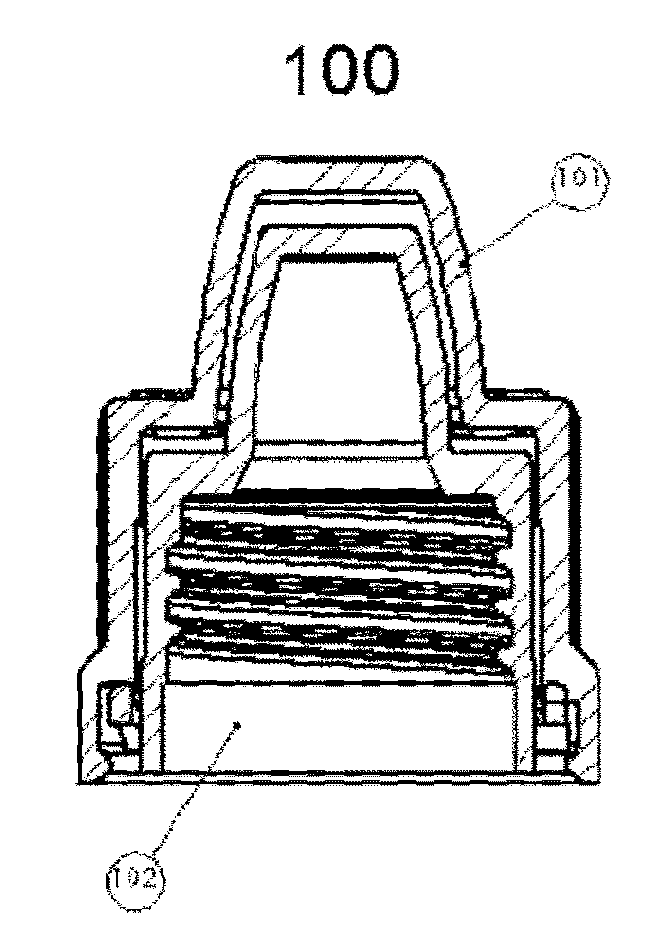
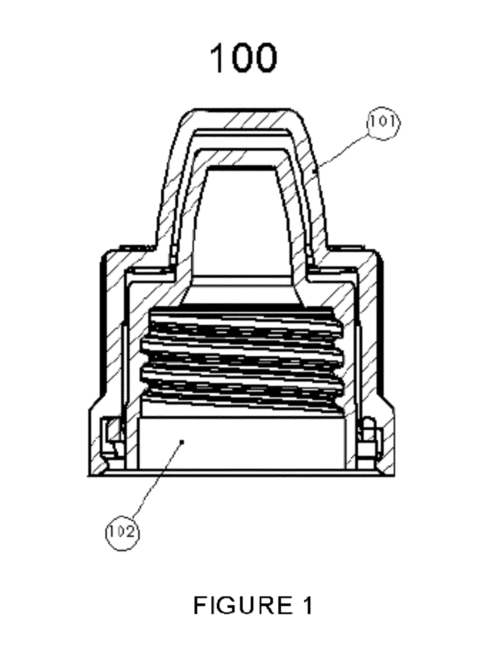
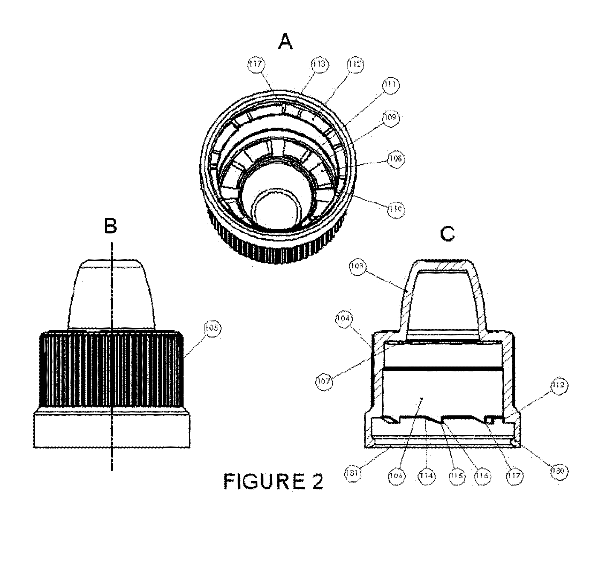
The present invention provides an improved child-resistant closure for liquid ophthalmic and nasal medicaments. The closure has a cap with matching numbers of complementary lugs and beams, and flexible beams with an angled ridge and arcuate underside. The beams have a predetermined distance or range of distances to ensure proper alignment. The closure ensures ideal frictional contact and prevents excess medicament pooling. The system has limitations on flexion of the beams to prevent damage. The methods for applying and removing the closure require no downward force, which reduces the likelihood of damage to the flexible beams and avoids miscalibration. The invention also provides a shaped top to minimize the internal volume available for unintentional pooling of excess medicament.

Problems solved by technology

If either the squeezing or rotating step is not performed, the cap cannot be opened.
However, several issues arose with implementation of prior art caps.
This lack of engagement allowed for slippage during the rotational process, which can lead to damage to the lugs, beams, and fingers of both the outer and inner caps.
Such damage often manifested itself in the form of stripping of the lugs, beams, and fingers.
However, the application of this downward force would often result in additional damage to the lugs, beams, or fingers.
This angled underside presented problems in that it would concentrate flexion at a very specific point which would often weaken the lug, beam, or finger.
When excess force is applied to flexible lugs, beams, or fingers, they are often forced to flex beyond their capabilities.
This hyper-flexion can result in a permanent deformation and even complete breakage of the lugs, beams, or fingers.
In lugs, beams, or fingers having an angled underside, breakage often occurred immediately above the angle.
Therefore, the cap is no longer child-resistant.
However, a major complaint of child-resistant caps has been that they are difficult for the elderly and infirm to remove.
With free-floating caps, the elderly often have a difficult time applying the appropriate amount of downward force necessary to get the appropriate lugs, beams, or fingers to engage.
Similarly, the elderly often have a difficult time maintaining the appropriate downward force throughout the rotational movement.
When applied to prior art caps, this lack of coordination and partial engagement would result in frustration on the part of the user.
Redoubled efforts often resulted in damage to the elements of the cap, through the combination of improper alignment and application of excess force, albeit briefly applied.
Additionally, when excess force is applied to a misaligned cap, portions of the cap may jam, requiring additional unconventional movements to clear the jam.
These unconventional movements may damage the cap, again leading to decreased, if not eliminated, child-resistance.
Similarly, an additional problem of prior art caps is that they require a downward force to apply them to a pre-existing bottle.
This is especially important to manufacturers, as machines capable of applying a downward force are more expensive than those which only apply a rotational force.
Work-arounds have been designed, however they are expensive and can often involve re-tooling of a machine, at a cost which eats into the profit margin of the manufacturer.
If the machine ventures too far beyond these tolerances, excess downward force may be applied to the cap as it is being affixed to the pre-existing bottle, and damage to the lugs, beams, and fingers may result.
The prior art caps are prone to damage resulting in loss of child-resistant qualities, and further, may unintentionally provide access to significant amounts of residual liquid medicament stored in the removed cap.

Method used


Image

  • Child-Resistant Cap for Liquid Medicaments
  • Child-Resistant Cap for Liquid Medicaments
  • Child-Resistant Cap for Liquid Medicaments

Examples


Embodiment Construction

[0024]For the purposes of the present disclosure, the term “overlap” shall be understood to mean the horizontal distance measured from the vertical plane of a lug face of a skirt lug to the vertical plane of the nearest beam face of a flexible beam, when the lug faces of shoulder lugs on inner and outer caps are aligned.

[0025]For the purposes of the present disclosure, the term “lug” shall be understood to include both male lugs and female lugs. Thus, discussion of “lugs” engaging one another shall be understood to include complementary male and female lugs engaging one another, two or more male lugs engaging one another, as well as two or more female lugs engaging one another. Similarly, discussions of flexible beams engaging lugs shall be understood to include engagement of male or female lugs by a flexible beam.

[0026]For the purposes of the present disclosure, the term “depth,” when referring to lugs, shall be understood to be a measure of the change in vertical length between a ...


PUM


Abstract

An improved child-resistant closure for dispensers of liquid medicaments, the closure being of a two-part construction. The closure has an outer cap with a quantity of shoulder lugs and skirt lugs and an inner cap with a quantity of shoulder lugs and flexible beams. The closure has equal quantities of shoulder lugs on the inner and outer caps, equal quantities of skirt lugs and flexible beams, flexible beams having an arcuate underside, shoulder lugs having a depth to prevent hyper-flexion of the flexible beams, and an ideal overlap when the faces of the shoulder lugs are aligned. Additionally, provided are methods for attaching and removing the cap from a pre-existing bottle.

Description

CROSS-REFERENCE TO RELATED APPLICATIONS[0001]This application claims priority to U.S. Provisional Application 61 / 671,194 filed on Jul. 13, 2012, which is incorporated herein in its entirety.FIELD OF THE INVENTION[0002]The invention relates to improvements to child-resistant closures for dispensers of liquid medicaments, in particular dispensers of liquid ophthalmic and nasal medicaments, and thereby provides enhanced safety of the dispensers by making the contents of the containers less susceptible to access by children.BACKGROUND OF THE INVENTION[0003]Child-resistant caps for medicaments have been known in the art for nearly fifty years. These caps generally require two opposed movements acting at the same time to overcome the locking mechanism. For example, one type of cap requires a user to squeeze the cap at specific points, causing a deformation, and then to rotate the cap. If either the squeezing or rotating step is not performed, the cap cannot be opened. Another common metho...

Claims


Application Information

Patent Timeline
Patent Type & Authority Applications(United States)
IPC IPC(8): B65D50/02
CPCB65D50/02B65D50/041
Inventor BUEHLER, JOHN D.DALY, JOHN B.DIPLACIDO, KEVIN A.HAROLD, REDD J.KERSHNER, DAVID T.MANERA, DAVID A.STANGLE, TIMOTHY K.GRANATO, RUSS
Owner COMAR
Learn More