Deterministic distributed network coding

a distributed network and coding technology, applied in data switching networks, frequency-division multiplexes, instruments, etc., can solve the problems of high complexity, complex prior deterministic network code designs, and high complexity, so as to improve the choice of coefficients, improve the rate of information delivery, and high complexity

a distributed network and coding technology, applied in data switching networks, frequency-division multiplexes, instruments, etc., can solve the problems of high complexity, complex prior deterministic network code designs, and high complexity, so as to improve the choice of coefficients, improve the rate of information delivery, and high complexity

US20140016469A1Active Publication Date: 2014-01-16CODE ON NETWORK CODING

Image

  • Deterministic distributed network coding
  • Deterministic distributed network coding
  • Deterministic distributed network coding

Examples


Embodiment Construction

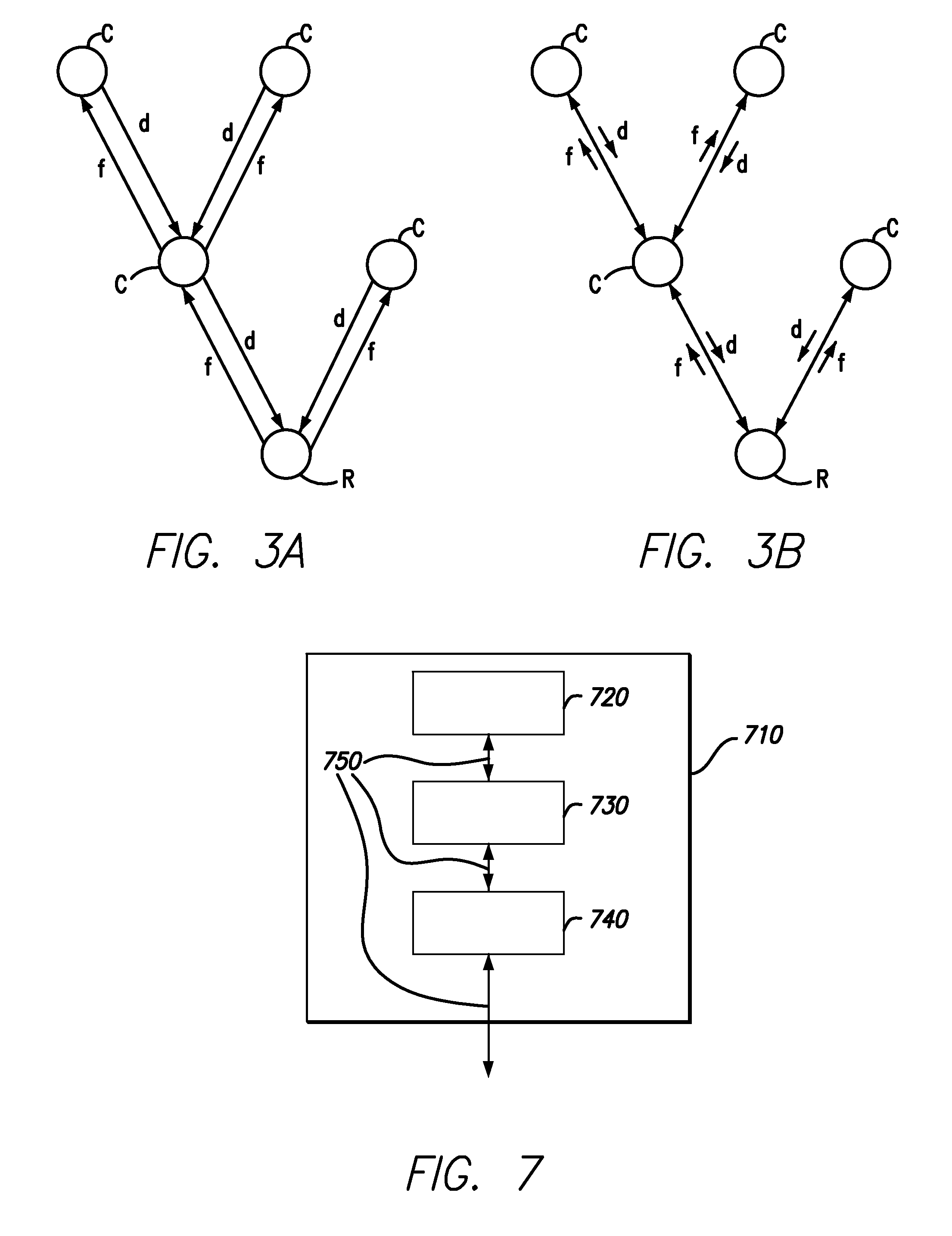
[0025]A first embodiment of the present disclosure concerns network coding over acyclic subgraphs of networks. Such acyclic subgraphs can be constructed using, for example, the techniques in D. S. Lun, N. Ratnakar, M. Medard, R. Koetter, D. R. Karger, T. Ho, and E. Ahmed, “Minimum-Cost Multicast over Coded Packet Networks,” IEEE Transactions on Information Theory, 52 (6), pp. 2608-2623, June 2006, incorporated herein by reference in its entirety. Data from the sources is transmitted over the acyclic subgraph to the receivers. If the network has bidirectional links or additional links in the reverse direction from the receiver nodes to intermediate nodes in the subgraph, feedback from the receivers can be used to improve the rate of information delivery.

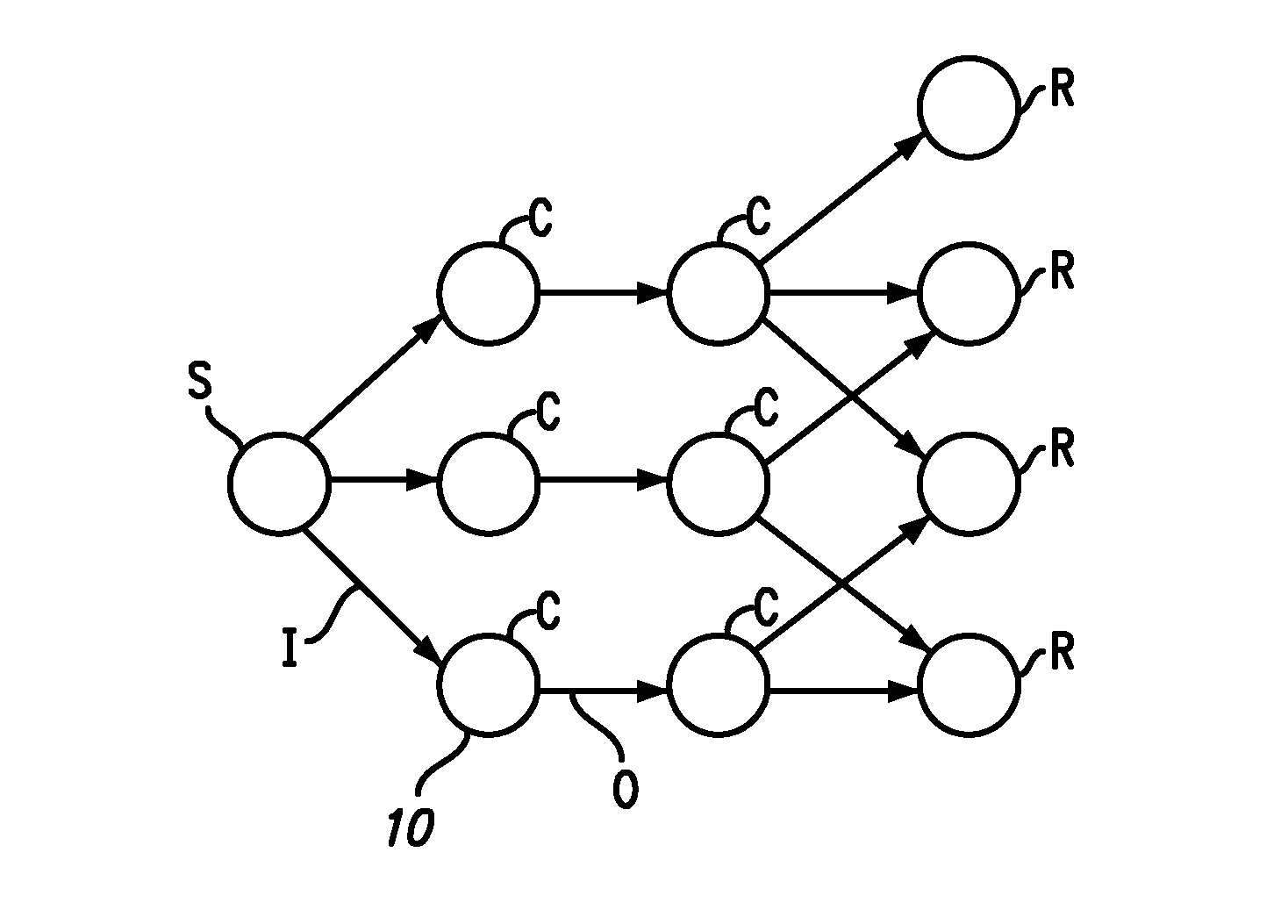
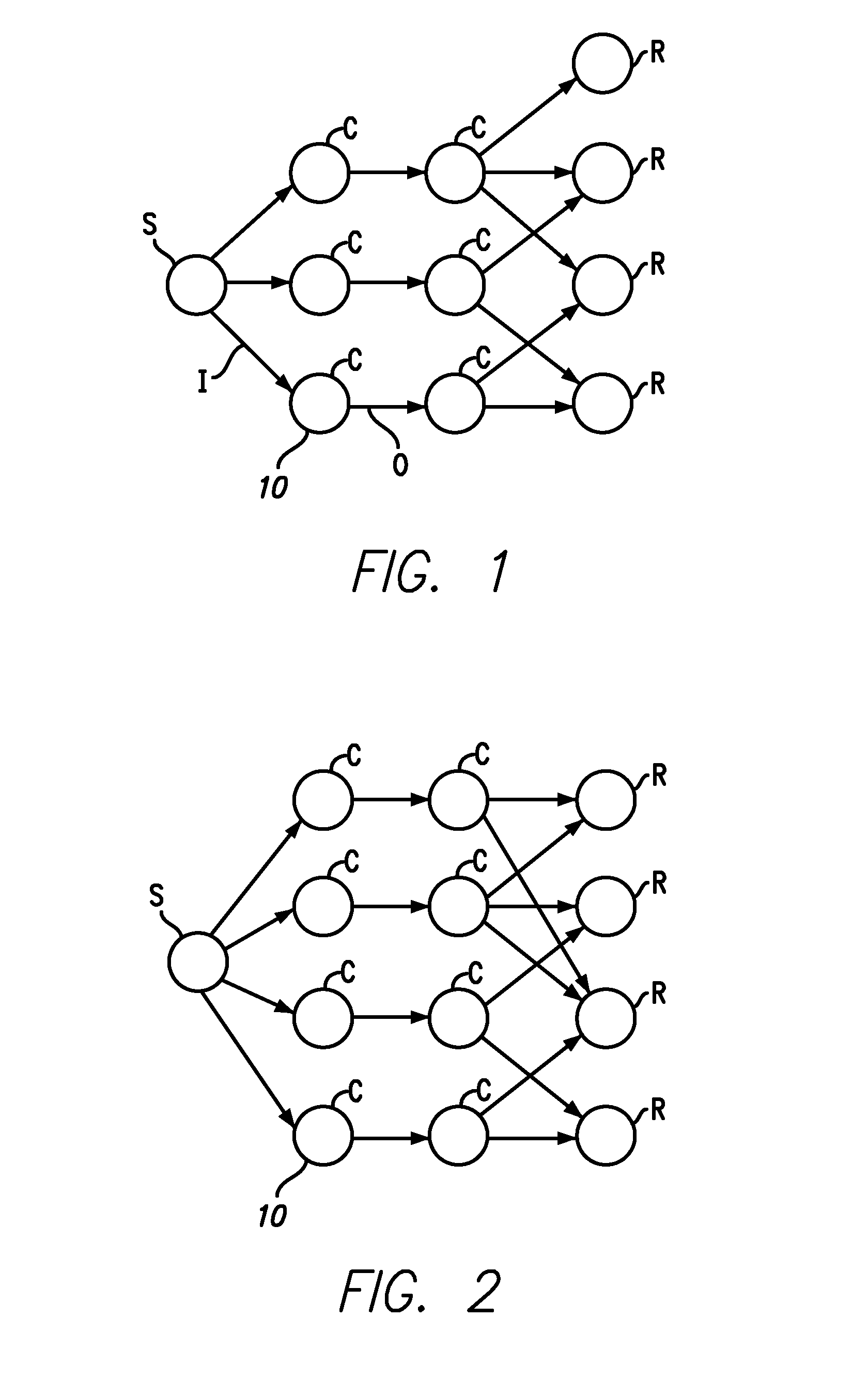
[0026]FIGS. 1 and 2 show two examples of acyclic networks having source nodes S and receiver nodes R, and a plurality of intermediate nodes C. The intermediate nodes allow communication of source processes to each receiver node R. The...


PUM


Abstract

A network and a communication method are described. The network comprises: source nodes, receiver nodes, and coding nodes. The coding nodes are connected with input links for communication of input signals to the coding nodes and output links for communication of output signals from the coding nodes. The output signals are a linear combination of the input signals. The coefficients of the linear combination are deterministically chosen based on local information available locally at the coding node.

Description

CROSS REFERENCE TO RELATED APPLICATIONS[0001]The present application claims priority to U.S. Provisional Application No. 61 / 672,208, filed on Jul. 16, 2012, which is incorporated herein by reference in its entirety. Furthermore, the present application may be related to U.S. Pat. No. 7,706,365, which is incorporated herein by reference in its entirety.BACKGROUND[0002]1. Technical Field[0003]Nodes in a computer network can also function as encoders. In particular, a node operating as encoder does not just forward (i.e. relay or replicate) information received from an input link, it also encodes such information. Coding at a node in a network is known as network coding.[0004]Networks can be modeled as graphs with unit capacity directed links, one or more discrete sources, and one or more receivers, as shown in R. Koetter and M. Medard, “An algebraic approach to network coding,” IEEE / ACM Transactions on Networking, Vol 11 Issue 5, October 2003, incorporated herein by reference in its e...

Claims


Application Information

Patent Timeline
16 Jan 2014
Publication
US20140016469A1
IPC
H04L12/811; H04W4/38
CPC
H04L47/38; H04L1/0076; H04L2001/0097; H04L1/0041; H04W4/38
Inventors
HO, TRACEY C.; EFFROS, MICHELLE