Passive safety system of integral reactor

a safety system and reactor technology, applied in the direction of nuclear reactors, nuclear elements, greenhouse gas reduction, etc., can solve the problems of high manufacturing cost, low injection flow rate, and large difficulty in solving problems of safeguard vessels, so as to improve safety of nuclear power plants, facilitate the operation, and maintain the water level in the reactor stably

Active Publication Date: 2014-01-16
KOREA ATOMIC ENERGY RES INST
View PDF4 Cites 55 Cited by
  • Summary
  • Abstract
  • Description
  • Claims
  • Application Information

AI Technical Summary

Benefits of technology

[0023]As described above, according to the passive safety system of an integral reactor of the present invention, facilities can be simplified since a safeguard vessel or an active pump is not necessary. In addition, upon an accident, water stored in the core makeup tank is supplied into the reactor by using a differential head resulting from gravity, the safety injection tank is connected with the reactor, so that the water in the safety injection tank is supplied into the reactor by the differential head resulting from gravity or gas pressure, thereby stably maintaining the water level in the reactor for many hours.
[0024]In addition, according to the passive safety system of the integral reactor of the present invention, the passive residual heat removal system is employed together, so that core residual heat can be stably removed for many hours upon an accident.
[0025]In addition, according to the passive safety system of the reactor of the present invention, the main safety system to maintain the integrity of the core is realized in a passive type, so that the safety of the nuclear power plant can be greatly improved.

Problems solved by technology

However, since a gravity tank such as the core makeup tank has a low gravitational head, an injection flow rate is low.
However, since the safeguard vessel is a pressure vessel that is smaller than a containment building (a containment vessel or a reactor building) but larger than a reactor, the safeguard vessel has a great difficulty in solving problems related to the manufacturing and the transporting of the vessel, the long term of construction works, the integrity of a device installed in the safeguard vessel under a high temperature and high pressure environment upon a loss of coolant accident, and the convenience in refueling and maintenance.
Accordingly, when the tank is manufactured in large size for the purpose of usage for many hours, the manufacturing cost is greatly increased, and the pressure boundary of the reactor is expanded.
In addition, since the safety injection tank is similar to that of the loop type active reactor, the safety injection tank is insufficient for the purpose of the usage for many hours.
Accordingly, the integral reactor has a difficulty in injecting external cooling water into the integral reactor by gravity without increasing the external pressure of the reactor (pressure balance) through a safeguard vessel.
As described above, since the pressurized-type safety injection tank applied to the commercial reactor must be designed at higher pressure, the manufacturing cost of the pressurized-type safety injection tank is greatly increased, and the safety injection is finished early (in the range from several tens of seconds to several minutes), so that the pressurized-type safety injection tank is not suitable for the integral reactor that must be actuated for many hours.
In addition, the active safety system has a difficulty in ensuring the reliability of a power supply system to actuate the above systems.

Method used


Image

  • Passive safety system of integral reactor
  • Passive safety system of integral reactor
  • Passive safety system of integral reactor

Examples


Embodiment Construction

[0032]The above and other objects, novel features and other advantages of the present invention will be more clearly understood from the following detailed description and accompanying drawings.

[0033]Hereinafter, the structure of the present invention will be described with reference to accompanying drawings.

[0034]The safety injection systems and the passive residual heat removal system (core makeup tank and safety injection tank) according to the invention may be provided as plural. Unless indicated otherwise, the safety injection system and the passive residual heat removal system may not exclude the meaning of plural.

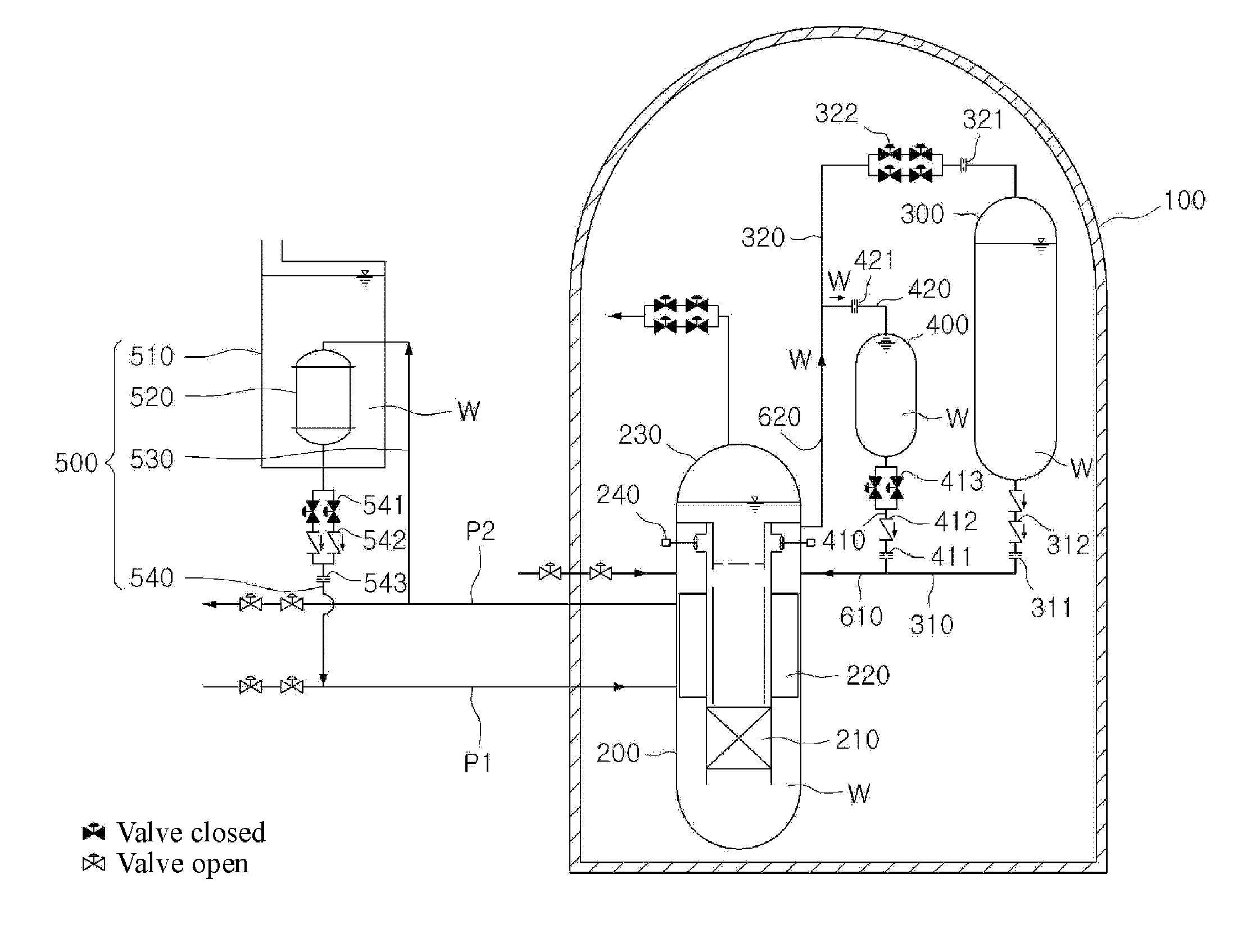
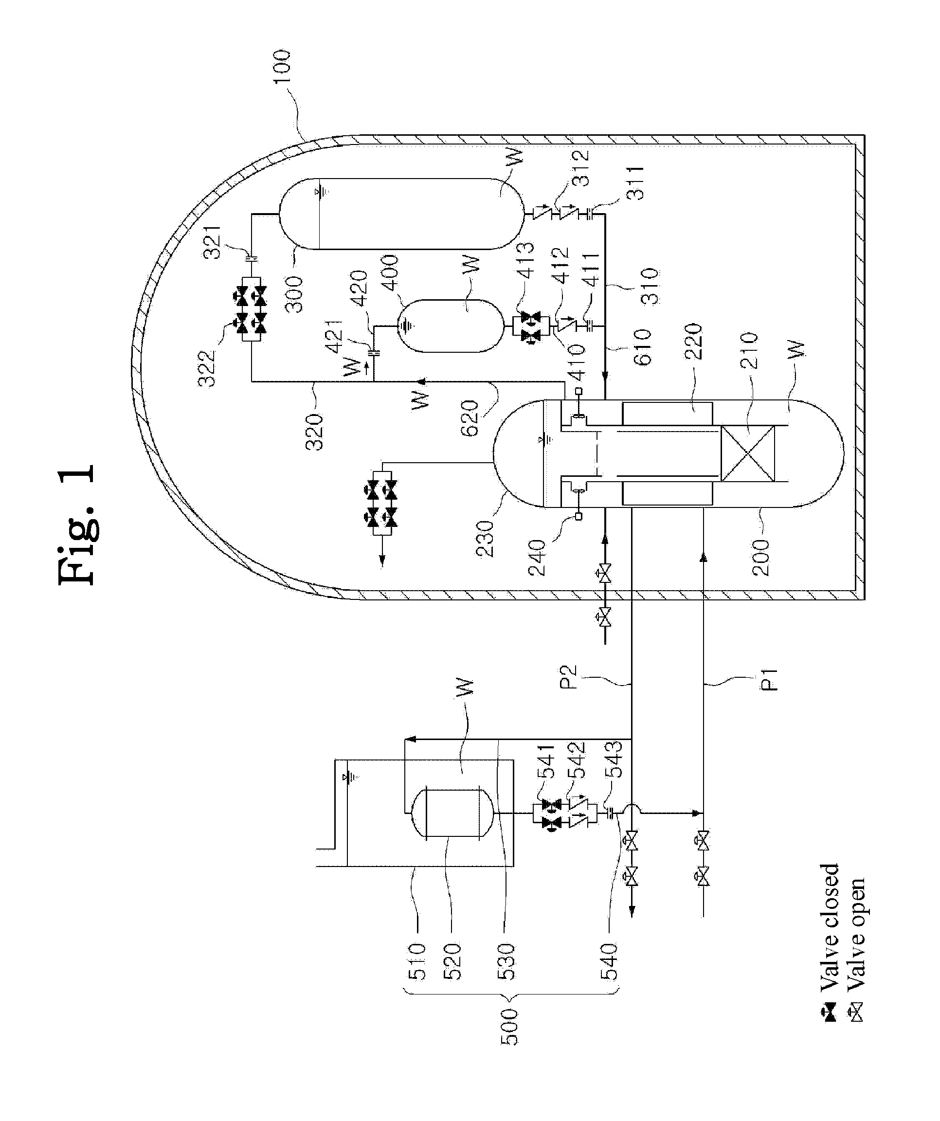
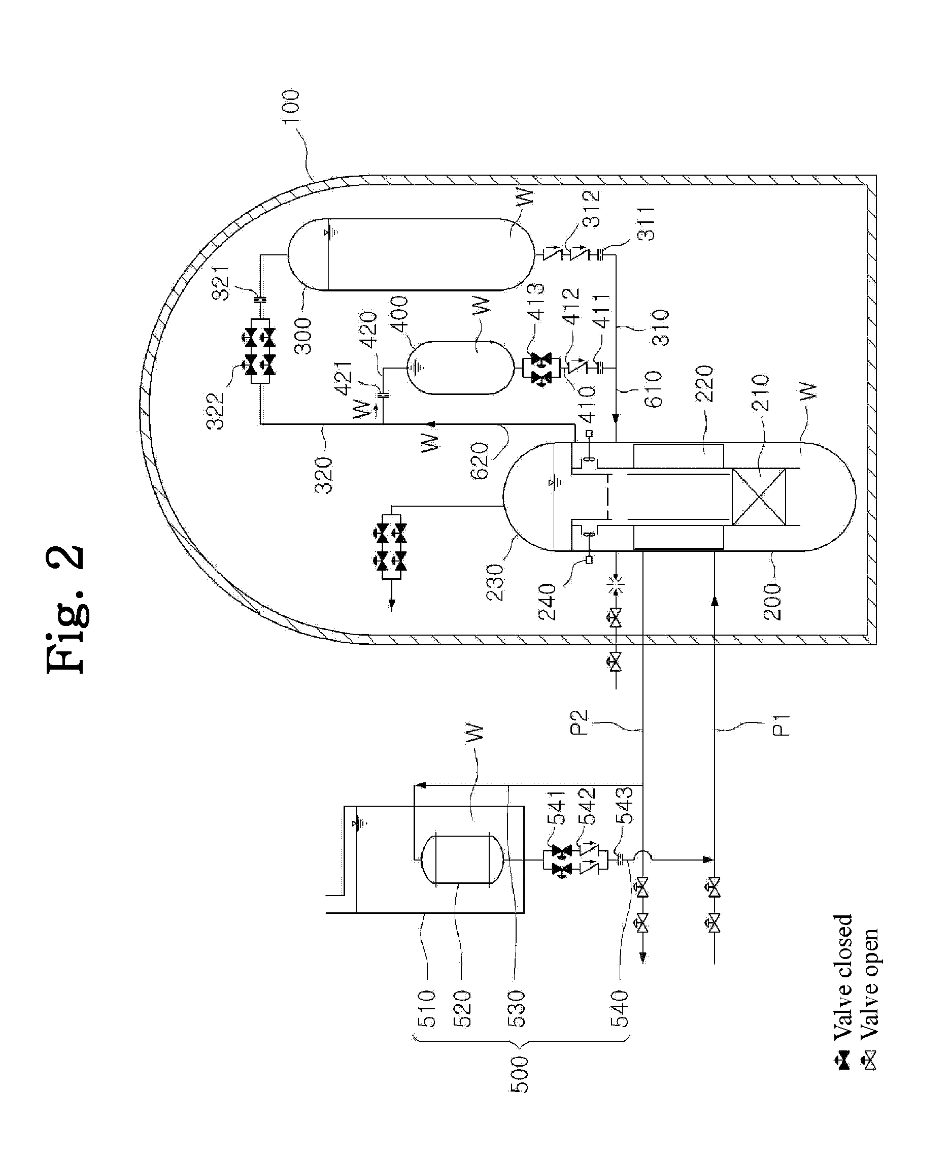
[0035]FIG. 1 is a view showing an example of applying a core makeup tank and a pressure balance-type safety injection tank in a passive safety system of an integral reactor according to the present invention. FIGS. 2 to 7 are views showing the actuating procedure of the passive safety system of the integral reactor of FIG. 1 according to the present invention when a ...


PUM


Abstract

A passive safety system includes a containment, a reactor in the containment, a plurality of safety injection tanks connected with the reactor and having water and nitrogen gas to supply water thereof into the reactor through a safety injection line communicating to the first safety injection line upon a loss of coolant accident, a plurality of core makeup tanks connected with the reactor to supply water thereof into the reactor through a second safety injection line communicating to a safety injection line upon the loss of coolant accident, and a plurality of passive residual heat removal systems to remove residual heat from the reactor upon the loss of coolant accident or a non-loss of coolant accident. The water in each of the safety injection tank is stably supplied to the reactor for many hours by a differential head resulting from gravity or gas pressure.

Description

BACKGROUND OF THE INVENTION[0001]1. Field of the Invention[0002]The present invention relates generally to a passive safety system of an integral reactor, and more particularly to a passive safety system of an integral reactor, which includes a passive safety injection system (core makeup tank and safety injection tank) and a passive residual heat removal system.[0003]In more detail, the present invention relates to a passive safety system capable of safely protecting a reactor by removing residual heat and maintaining a core water level in a reactor by using natural force such as gas pressure or gravity without active equipment such as a safety injection pump, which requires power supply, or a facility such as a safeguard vessel for a considerable amount of time at which the residual heat emitted from a reactor core is significantly reduced.[0004]2. Description of the Related Art[0005]Different from a typical industrial power plant, a nuclear power plant generates residual heat fro...

Claims


Application Information

Patent Timeline
Patent Type & Authority Applications(United States)
IPC IPC(8): G21C15/18
CPCG21C15/18G21C1/32Y02E30/00Y02E30/30G21C9/00G21D3/04
Inventor MOON, JOO HYUNGLEE, WON JAEKIM, KEUNG KOOPARK, CHEON TAEKIM, YOUNG INZEE, SUNG KYUNPARK, KEUN BAE
Owner KOREA ATOMIC ENERGY RES INST
Why Eureka
Try Eureka