Diathermy Applicator Garment

Active Publication Date: 2014-01-16
VIATHERM THERAPEUTICS LLC
View PDF2 Cites 3 Cited by
  • Summary
  • Abstract
  • Description
  • Claims
  • Application Information

AI Technical Summary

Benefits of technology

[0010]An object of the invention is the reduction local surface burning during treatment by improvin

Problems solved by technology

Patients undergoing diathermic deep-heating treatment occasionally experience superficial burning to the skin surrounding the area of intended treatment, similar to sunburn.
However, for an entirely different reason, patients occasionally experience superficial burning, somewhat resembling a sunburn.
Solutions entail

Method used


Image

  • Diathermy Applicator Garment
  • Diathermy Applicator Garment
  • Diathermy Applicator Garment

Examples


Embodiment Construction

[0037]Applicants have inventively discovered that an appreciation of the precise dynamics of these fields and the attendant thermal flow leads to a clear determination of an optimal spacing for the wire winding. For one thing, diathermy employs RF stimulation, [see below: which is known not to be Conservative / Laplacian]. Thus the deformation of the spatial RF distribution under changing geometry must be treated differently and is more involved than the heat distribution.

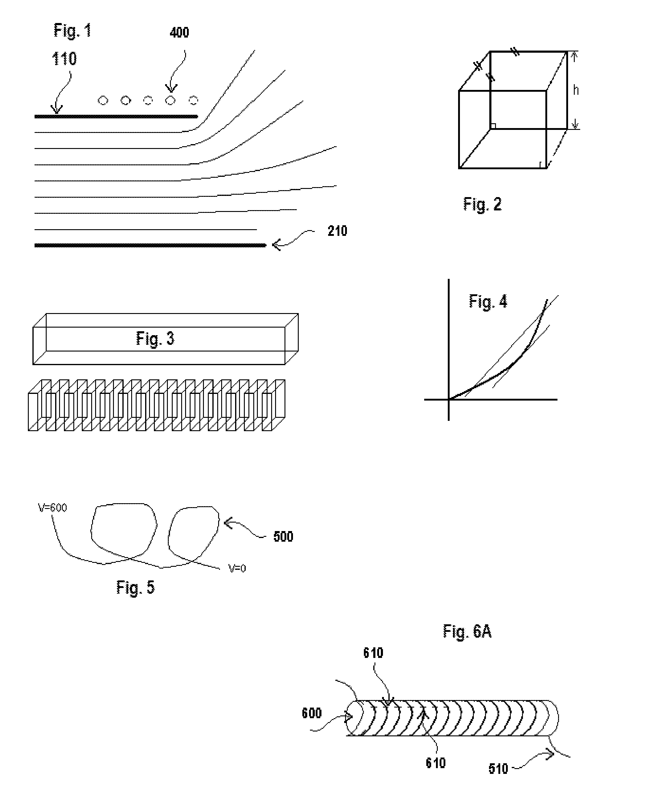
[0038]The surface with constant temperature may be regarded as a thermal boundary and deformations or other geometrical circumstances will be well-modeled by a conformal mapping of the heat distribution imposed by this boundary 110, regardless of the cause of the thermal boundary or its distribution along the length of the fabric, (or along a radial line, for the back garment) as shown in FIG. 1.

[0039]All (three) of the quantities in question in the present application of diathermic deep-heating all obey Laplacian ru...


PUM


Abstract

A therapeutic diathermy applicator is proposed which minimizes the common problem of burning of skin patient. The heat distribution arising as a result of unwanted capacitive effects is modeled as a manifestation of ‘conservative’ energy. A specific spatial characteristic of RF stimulation is determined and incorporated into the design of the applicator in order to achieve these goals.

Description

[0001]The present invention pertains to improvements to manufacturing and operational methods for therapeutic diathermy treatment applicators as presented in prior commonly assigned U.S. Pat. Nos. 6,853,865, 7,953,500 and 8,489,201, all of which are herein expressly incorporated by reference in their entirety for essential subject matter.[0002]The present invention relates to the field of diathermic treatment applicators.GLOSSARY[0003]Arg(z) angle of principle value of a complex number. (0< / =Arg(z)< / =2π)[0004]Angles are given in radians unless otherwise noted.Cauchy-Reimann Theorems pertaining to harmonic functions.Conformal mapping: Complex mappings in which angles are preserved from the preimage region to the image region.Derivative: slopeelbow: a point at which a curve changes direction abruptly Euler's formula eiθ=cos θ+i sin θ thus eπi=−1EQS=electroquasistatic refers to oscillating electric fields which nevertheless retain many useful characteristics of static electric fi...

Claims


Application Information

Patent Timeline
IPC IPC(8): A61B18/18
CPCA61B18/18A61N1/403A61N2/02
Inventor UNETICH, ROBERT M.VIRANY, LESLIE R.J.
Owner VIATHERM THERAPEUTICS LLC
Why Eureka
Try Eureka