
Computer implemented electrical energy hub management system and method

a technology of electrical energy hub and management system, applied in the field of energy management, can solve the problems of insufficient attention to the ways in which the hub can be operated to maximize, and achieve the effect of optimizing energy utilization and optimizing energy utilization

Active Publication Date: 2014-01-16
RODAN ENERGY SOLUTIONS INC
View PDF3 Cites 76 Cited by
  • Summary
  • Abstract
  • Description
  • Claims
  • Application Information

AI Technical Summary

Benefits of technology

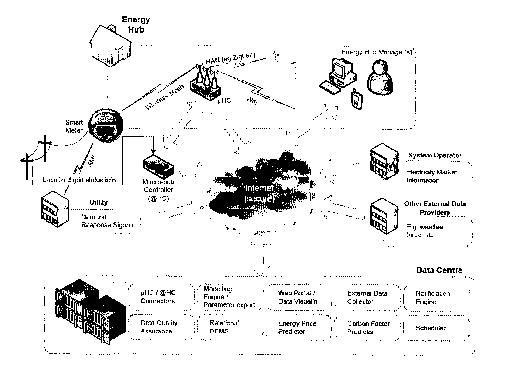
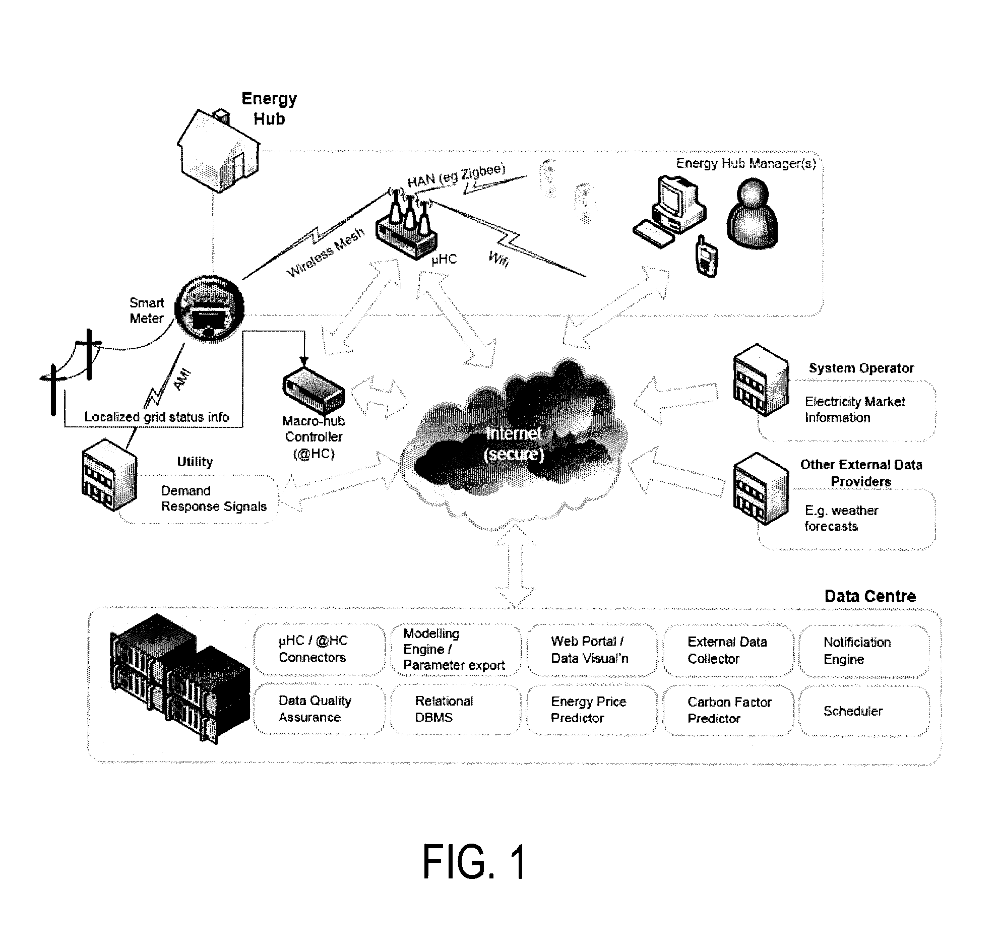
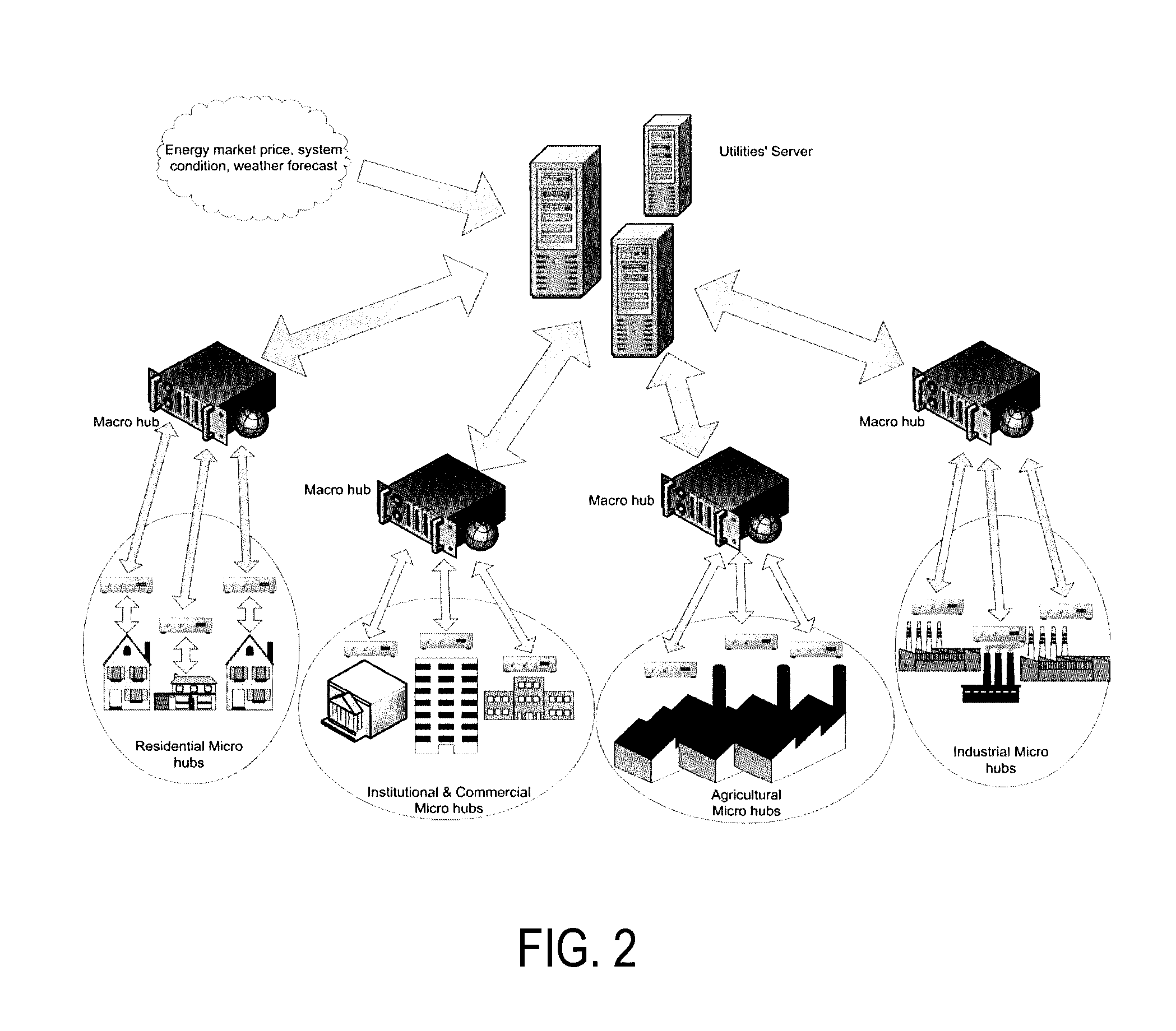
This patent describes a system and method for managing energy usage at a premise. The system includes an energy hub that interfaces with various energy devices and an energy optimization engine that receives data from the energy devices and external sources. The engine analyzes the data and generates an energy model to optimize energy usage based on user preferences and external restrictions. The energy hub can control the energy devices and act as a bridge to the energy grid. The technical effects of this system include improved energy utilization, cost savings, and reduced energy waste.

Problems solved by technology

While individual energy efficiency and renewable energy technologies continue to be developed in ever-improving ways, insufficient attention is being paid to the ways in which they can be operated to maximize the benefits across a broader ‘energy system’.
In industrial locations, the fact that energy can be a significant cost to some companies has meant that it is monitored closely and, therefore, industrial customers have traditionally been those first to respond to ‘demand response’ programs.

Method used


Image

  • Computer implemented electrical energy hub management system and method
  • Computer implemented electrical energy hub management system and method
  • Computer implemented electrical energy hub management system and method

Examples


examples

[0127]Energy component models of major household devices (appliances), i.e., air-conditioning, heating system, water heater, pool pumps, fridge, dishwasher, washer and dryer, and stove are provided herein. Also, a generic energy component model for energy storage / generation devices, and an energy component model of a photo-voltaic (PV) solar array is provided. These set of energy component models represent the operational constraints of the residential energy hub. The definition of the model variables and sample parameter values are:

DescriptionExampleIndicesiDevice (Appliance)i = FR, i = ACtTime intervalt = 1, 2, 3, . . . , 96SetsASet of devices (appliances){FR, AC, H, DW, W}TSet of indices in the scheduling horizonT = {1 . . . 96}TiTi ⊂ T is the set of periods in which device i mayTAC = {1 . . . 96}operate; Ti = {t ∈ T: EOTi ≦ t ≦ LOTi}VariablesSi(t)State of device i at time t, binaryOn / OffUi(t)Binary variable denoting start up of device i at time t:0 / 1Ui(t)={1startupofdeviceiattim...


PUM


Abstract

There is disclosed a system, computer program and method provided for enabling an energy hub for improved management and optimization of energy utilization (consumption, production and storage). In an embodiment, a computer-implemented energy hub management system comprises a micro energy hub configured to communicate with two or more energy components at a premises. An energy optimization engine has an energy component model for each energy component based on each energy component's operating characteristics, the energy optimization engine adapted to receive at least one input from the two or more energy components and an input from an external data source on any external energy utilization restrictions for the micro energy hub. In response to at least one input from the two or more energy components and any external energy utilization restrictions on the micro energy hub, the energy optimization engine is adapted to issue one or more control signals to at least one of the energy components at the premises to optimize energy utilization based on one or more optimization criteria.

Description

CROSS-REFERENCE TO RELATED APPLICATIONS[0001]This application claims priority from U.S. Provisional Patent Application No. 61 / 470,098 filed on Mar. 31, 2011.FIELD OF THE INVENTION[0002]The present invention relates generally to energy management. The present invention relates more specifically to a platform for providing an energy hub that is operable to manage energy usage at a particular premise that comprises a plurality of energy components, including energy consuming components, energy storing components and / or energy producing components.BACKGROUND OF THE INVENTION[0003]While individual energy efficiency and renewable energy technologies continue to be developed in ever-improving ways, insufficient attention is being paid to the ways in which they can be operated to maximize the benefits across a broader ‘energy system’. Significant effort, for example, is being exerted in order to improve the efficiency of photovoltaic cells from, for example, 15% to 18%. What is less recogni...

Claims


Application Information

Patent Timeline
IPC IPC(8): G06F1/26
CPCG06F1/26G06Q10/04G06Q50/06Y02B70/3225Y04S20/222Y04S20/242H02J2310/64H02J2310/14H02J2300/24H02J3/381H02J3/14Y02B70/30Y02E10/56Y04S50/10
Inventor ELLIS, GORDON D.CANIZARES, CLAUDIO ADRIANBHATTACHARYA, KANKARCHEHREGHANI BOZCHALUI, MOHAMMADHASSEN, HUSSINHASHMI, SYED AHSAN
Owner RODAN ENERGY SOLUTIONS INC
Learn More