
A method and a system for optimising energy usage at a drilling arrangement

a drilling arrangement and energy consumption technology, applied in the direction of programme control, instruments, borehole/well accessories, etc., can solve the problems of damage, energy might not be enough to dislodge stones from the rock, energy might be transferred into unnecessary kinetic energy of dislodged stones, etc., to achieve easy optimization of energy usage, low complexity of system, and great influence on energy usage

Active Publication Date: 2018-10-04
LKAB WASSARA AB
View PDF4 Cites 0 Cited by
  • Summary
  • Abstract
  • Description
  • Claims
  • Application Information

AI Technical Summary

Benefits of technology

This patent describes a method for determining the energy usage of a drilling arrangement based on a single input parameter, namely the acceleration. This reduces the complexity of the system and makes it easier to optimise energy usage. The method also allows for real-time feedback on energy usage, which is useful for operators. Additionally, the patent describes a technique for determining the main drilling frequency, which is a significant factor in energy usage. This can be done using a cepstrum method to prevent incorrect identification of overtones. The method can be applied while drilling, without the need for additional analysis time.

Problems solved by technology

If the energy transfer from a drilling arrangement to the rock is too low, the energy might not be enough to dislodge stones from the rock and the energy is mainly transformed into heating of the rock and the drilling arrangement.
If the energy transfer from the drilling arrangement to the rock is too high, the energy might be transferred into unnecessary kinetic energy of the dislodged stone.
When not using the energy efficiently, overshoot energy might also cause damages at the drilling arrangement.
Such damages can, for example, be caused by increased wear.
This can be due to the overshoot energy being transferred to the drilling arrangement via additional vibrations, heat, and / or strikes.
Although being a useful parameter, the MSE has the drawback that it is not easy to determine.
This results in increased complexity of the drilling arrangement.
Another drawback of the MSE is that the different sensors relate to different parameters which all can be optimised.

Method used


Image

  • A method and a system for optimising energy usage at a drilling arrangement
  • A method and a system for optimising energy usage at a drilling arrangement
  • A method and a system for optimising energy usage at a drilling arrangement

Examples


Embodiment Construction

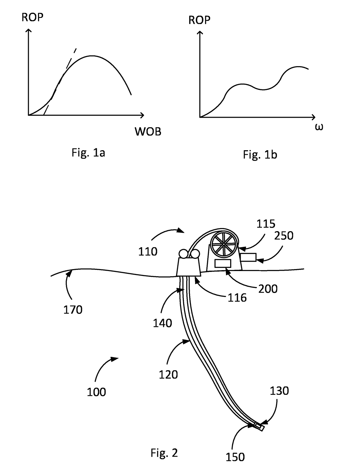
[0040]In FIG. 1a a possible behaviour between the so-called weight on bit, WOB, i.e. the amount of downward force placed on a bit, and the so-called rate of penetration, ROP, i.e. the speed at which the bit drills into a formation, is schematically shown. With low WOB the downward force might not be enough to cut the formation efficiently. The term formation can relate to rock, stone, or any other material in which the drilling operation should be performed.

[0041]After a certain ramping-up period, an increased WOB will increase the ROP approximately linear as is indicated by the dashed line in the FIG. 1a. For increasing the ROP one can thus increase the WOB. Above a certain amount of WOB, however, the ROP will increase with lower and lower slopes. Above another certain amount of WOB, the ROP will eventually decrease. The lowering of the slope and the eventual decrease can be caused by a balling of a drill bit, by a balling of a bottom hole assembly, BHA, by vibrations, by a reduced...


PUM

PropertyMeasurementUnit
Accelerationaaaaaaaaaa
Frequencyaaaaaaaaaa
Energyaaaaaaaaaa

Abstract

The present invention relates to a method for optimising energy usage at a drilling arrangement. The method includes the step of determining an acceleration of a drilling head in the drilling arrangement. The method further includes determining a parameter related to the energy usage at the drilling arrangement based on the determined acceleration. The method even further includes optimising the energy usage based on the determined parameter. The present invention also relates to a system for optimising energy usage at a drilling arrangement, to a computer program, and to a computer program product.

Description

TECHNICAL FIELD[0001]The present invention relates to a method and a system for optimising energy usage at a drilling arrangement. The present invention further relates to a computer program for optimising energy usage at a drilling arrangement and to a computer program product.BACKGROUND ART[0002]When drilling, a lot of energy is used for the drilling process. It is thus of interest that the energy is used in an efficient way. A way of measuring the energy efficiency is to look at how much rock is destroyed or how much stone is dislodged from the rock for a given amount of energy. Further, one can look at how much energy is needed to remove the dislodged rock out of the drilling hole. If the energy transfer from a drilling arrangement to the rock is too low, the energy might not be enough to dislodge stones from the rock and the energy is mainly transformed into heating of the rock and the drilling arrangement. It might also be that the energy is enough to dislodge stones, but not ...

Claims


Application Information

Patent Timeline
IPC IPC(8): E21B41/00G05B13/02G06F17/14
CPCE21B41/0092G05B13/024G06F17/141E21B45/00E21B1/00E21B44/00E21B44/02G05B15/02B23B39/00G05B2219/45129E21B41/00
Inventor PECO, THIMAQ TIM
Owner LKAB WASSARA AB
Learn More