Feeding control mechanism of packaging machine

a control mechanism and packaging machine technology, applied in mechanical conveyors, packaging, loading/unloading, etc., can solve the problems of deteriorating the overall operation efficiency of the packaging machine, increasing labor costs, and inability to handle these products, and achieves smooth performance of the subsequent packaging process

Inactive Publication Date: 2014-01-23
HUNG TZU CHIN
View PDF0 Cites 9 Cited by
  • Summary
  • Abstract
  • Description
  • Claims
  • Application Information

AI Technical Summary

Benefits of technology

[0006]Thus, the primary object of the present invention is to provide a novel feeding control mechanism of packaging machine, which is for dedicated use in a feeding terminal of a...

Problems solved by technology

The conventional packaging machines are generally not capable enough to handle these products.
This ...

Method used


Image

  • Feeding control mechanism of packaging machine
  • Feeding control mechanism of packaging machine
  • Feeding control mechanism of packaging machine

Examples


Embodiment Construction

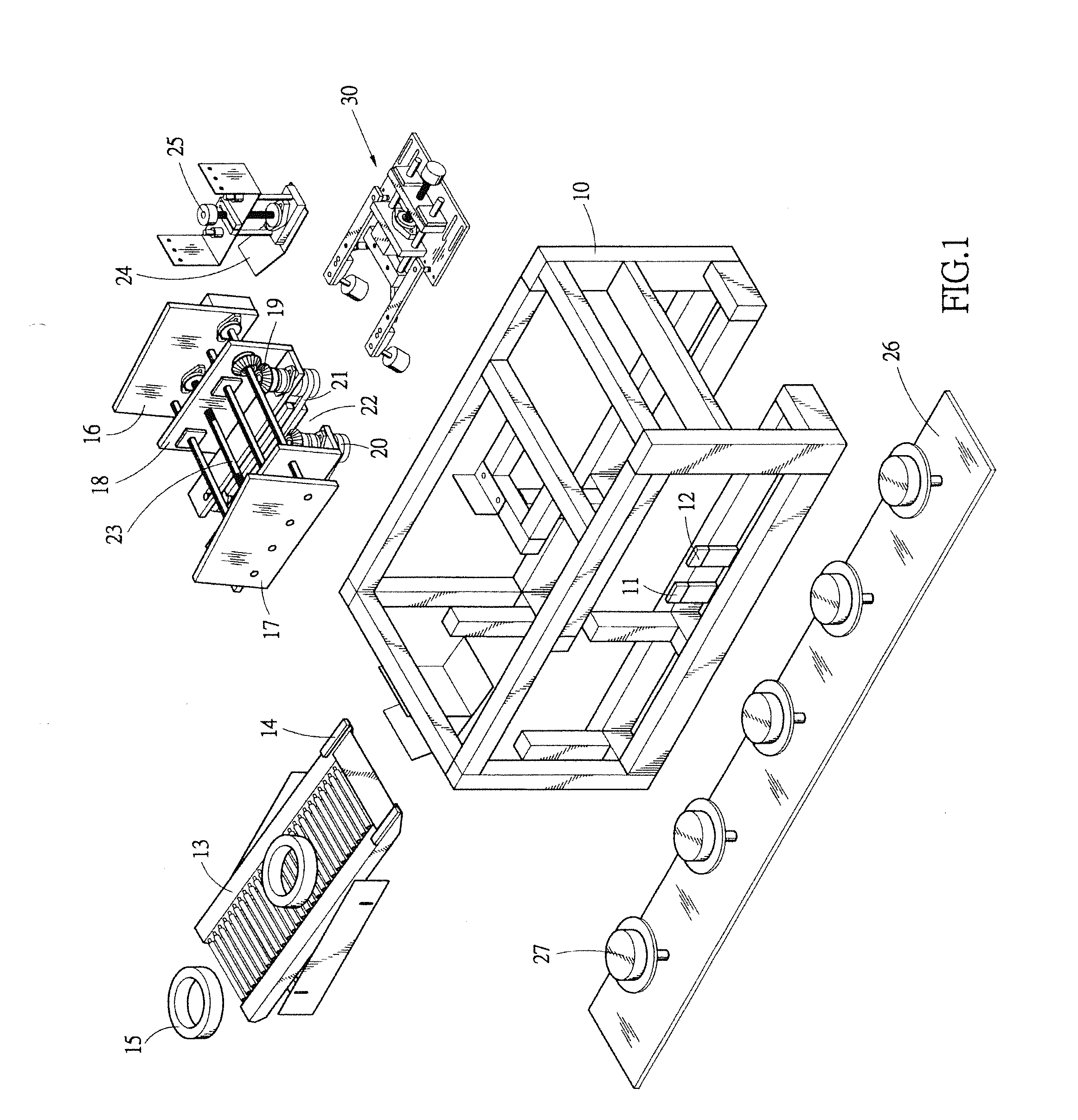
[0021]FIG. 1 of the attached drawings is an exploded view of a feeding control mechanism of packaging machine according to the present invention.

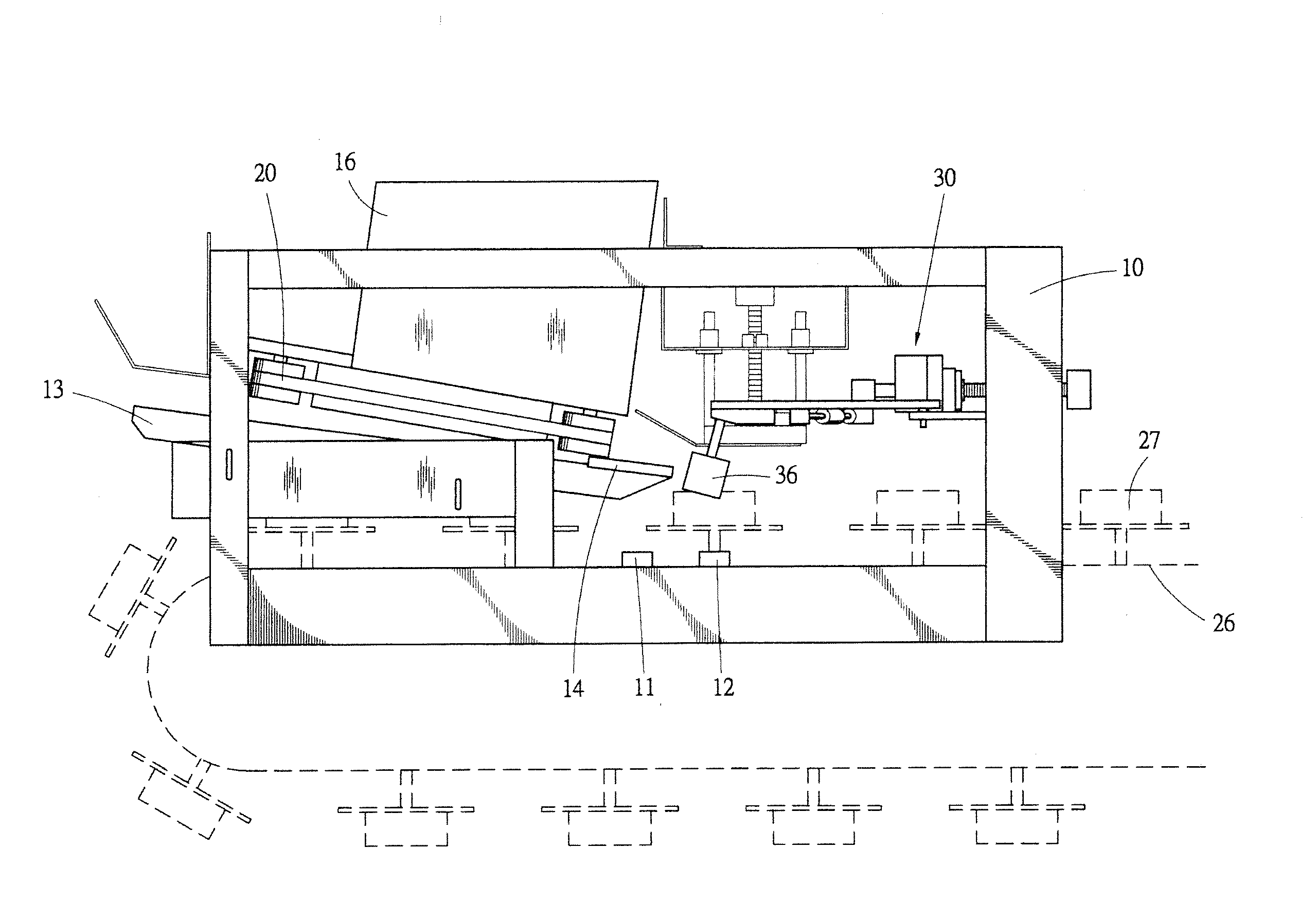
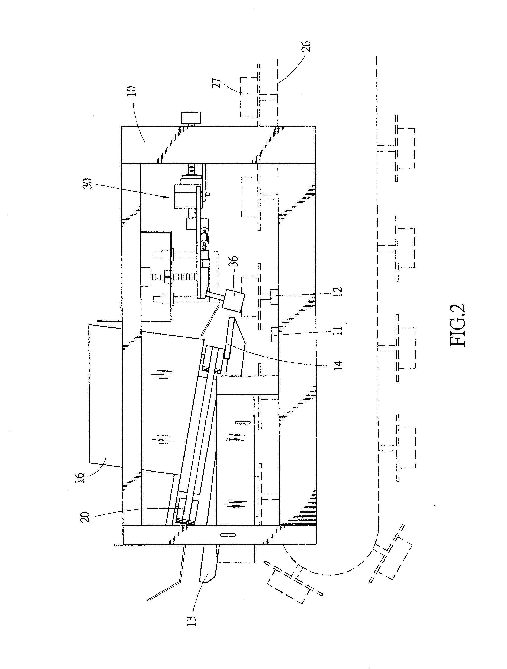
[0022]FIG. 2 is a side elevational view of the feeding control mechanism of packaging machine according to the present invention.

[0023]As shown in FIGS. 1 and 2, the feeding control mechanism of packaging machine according to the present invention generally comprises a chassis 10, a feeding guide 13, a forwarding device 16, a conveyor belt 26, and a feeding controller 30.

[0024]As shown in FIG. 1, the chassis 10 supports various components of the feeding control mechanism mounted thereon, including a first sensor 11 and a second sensor 12 that are mounted along one side of a moving path of a conveyor belt 26 mounted in the chassis 11 to detect product trays 27 of the conveyor belt 26.

[0025]As shown in FIG. 1, the feeding guide 13 is arranged at a front side of the chassis 10. The feeding guide 13 has a surface at one side of which a feed-in ...


PUM


Abstract

A feeding control mechanism of packaging machine includes a chassis, a feeding guide, a forwarding device, a conveyor belt, and a feeding controller. The feeding guide is arranged at a front side of the chassis to forward a product into the chassis. The forwarding device includes a feeding channel defined by left and right pulleys for clamping and moving a product onto a conveyor belt. The feeding controller is arranged above the conveyor belt. The product tray carried by the conveyor belt are used to trigger first and second sensor of the chassis to activate the feeding controller for opening/closing stop pegs so as to control each product to be correctly positioned on each product tray of the conveyor belt.

Description

BACKGROUND OF THE INVENTION[0001]1. Field of the Invention[0002]The present invention relates to a feeding control mechanism of packaging machine, and in particular to feeding control mechanism that is used at a feeding terminal of various heat sealing packaging machines to control products to be correctly positioned on product trays of a conveyor belt.[0003]2. The Related Arts[0004]A heat sealing packaging machine is large-sized automatic packaging machinery commonly used in the industrial sector for packaging an object that is manufactured as merchandise with a shrink film and subjecting the packaged object to heating with high temperature air in order to have the shrink film heated and tightly shrink-wrapped the merchandise object. This provides a number of advantages for the packaged object, including improved product stability, better weather durability, easy warehousing and shipping, and protection of outside appearance from undesired damage.[0005]However, there are a huge num...

Claims


Application Information

Patent Timeline
IPC IPC(8): B65G17/12
CPCB65B35/16B65B35/24B65B57/14B65B59/005B65G65/00B65B59/001
Inventor LIAO, BENISON
Owner HUNG TZU CHIN
Why Eureka
Try Eureka