Compensating Hysteresis Bands to Hold Specified Switching Frequency

a technology of switching frequency and compensation band, applied in the direction of control system, electrical apparatus, ac motor control, etc., can solve the problems of increased power loss, limited adjustment of chopping scheme, and increased operational temperatur

Active Publication Date: 2014-01-23
CATERPILLAR INC
View PDF5 Cites 4 Cited by
  • Summary
  • Abstract
  • Description
  • Claims
  • Application Information

AI Technical Summary

Problems solved by technology

However, adjustments in the chopping scheme are limited due to various hardware constraints.
Among other things, the switching frequency as well as the turn-off point for each phase cannot be adjusted without adversely affecting machine components, thus leaving only the turn-on point of each phase as a point of adjustment.
However, use of such techniques often results in higher currents, which further leads to increased losses in power, higher operational temperatures and increased risks of over-current conditions.
However, due to machine inductance, current rise rates, and in some instances, current fall rates, the lower limit of the hysteresis band can exhibit a drooping effect.
Such decreases in the average phase current further lead to lower average torque production and an overall reduction in torque accuracy.

Method used


Image

  • Compensating Hysteresis Bands to Hold Specified Switching Frequency
  • Compensating Hysteresis Bands to Hold Specified Switching Frequency
  • Compensating Hysteresis Bands to Hold Specified Switching Frequency

Examples


Embodiment Construction

[0019]Reference will now be made in detail to specific embodiments or features, examples of which are illustrated in the accompanying drawings. Generally, corresponding reference numbers will be used throughout the drawings to refer to the same or corresponding parts.

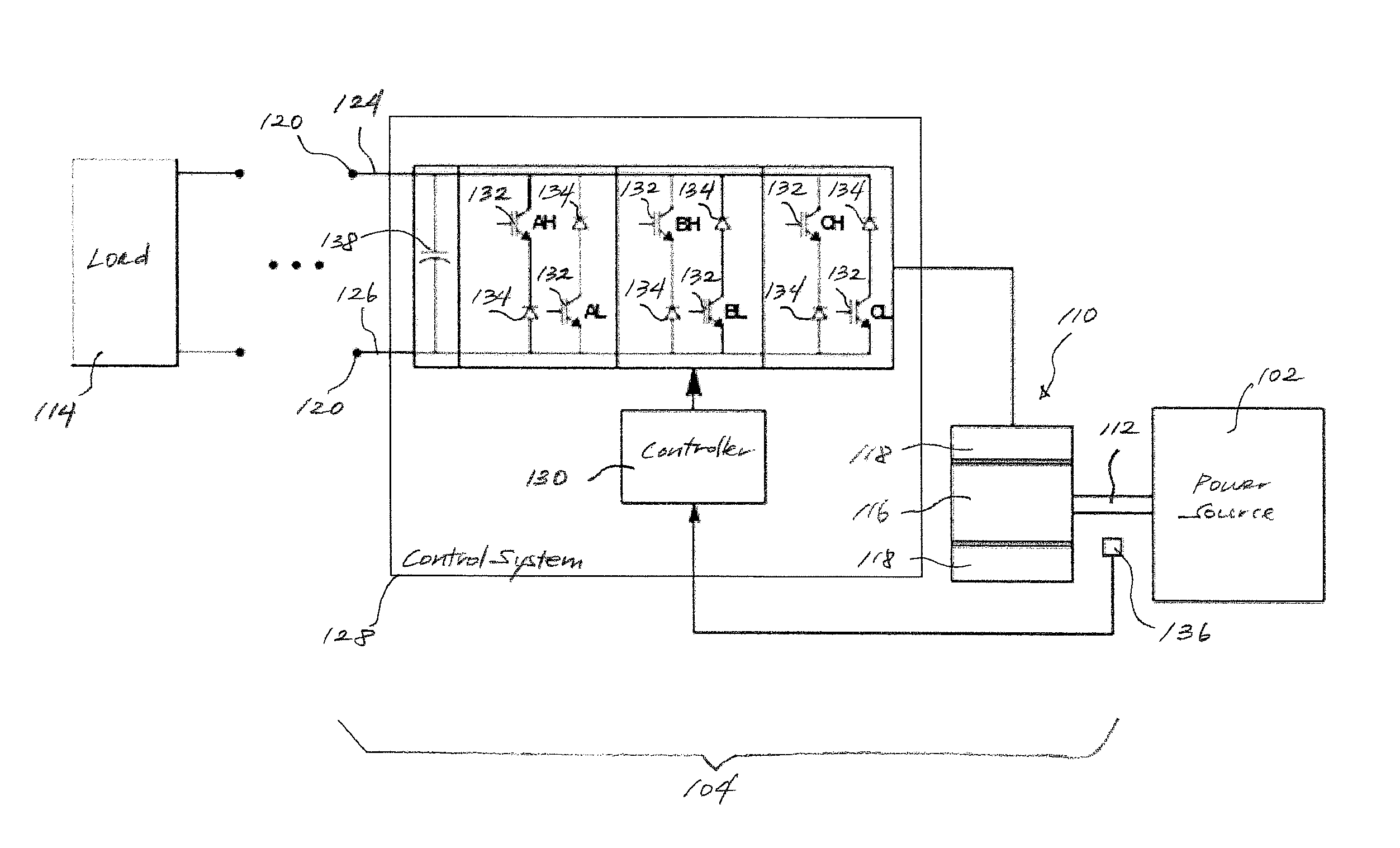
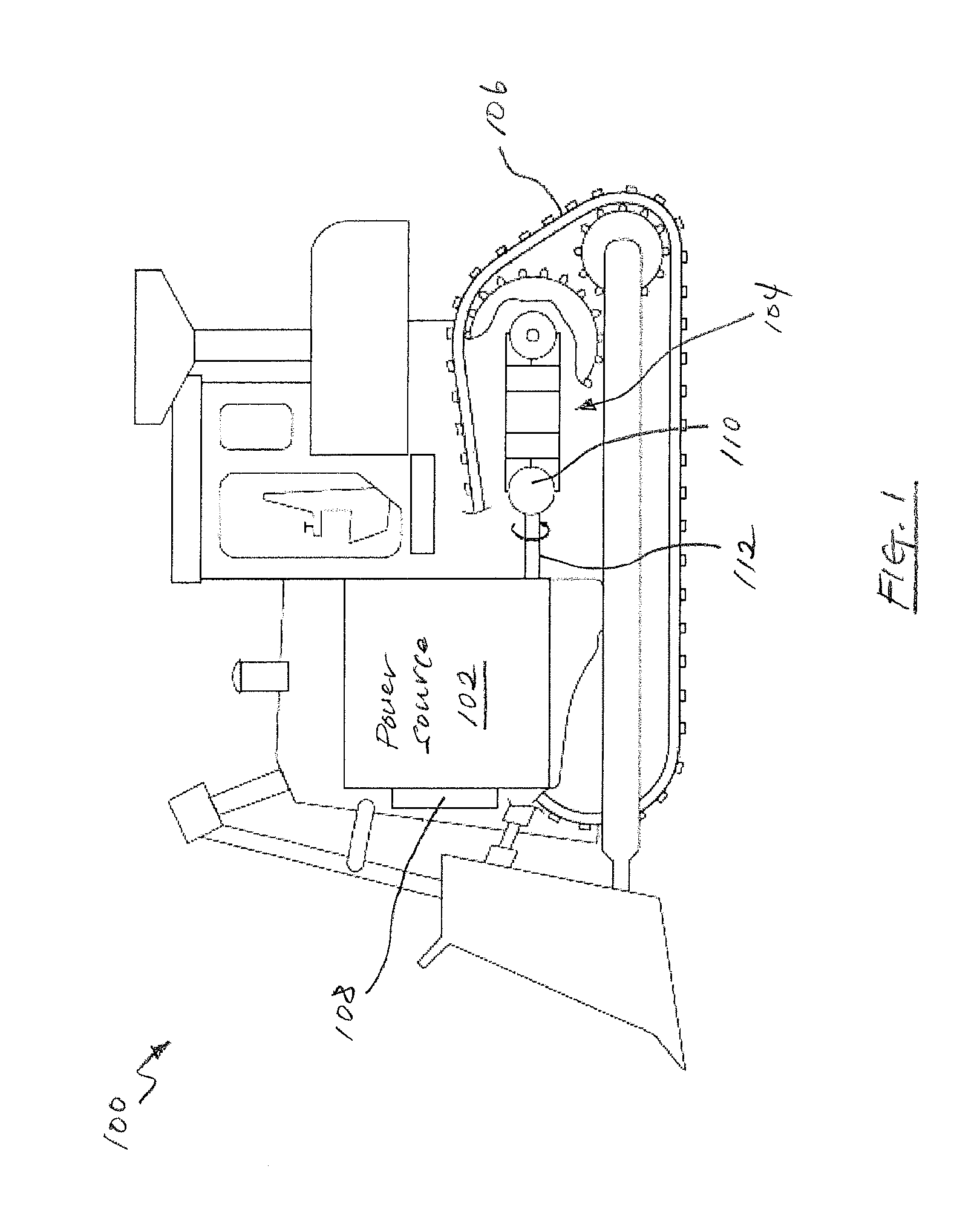
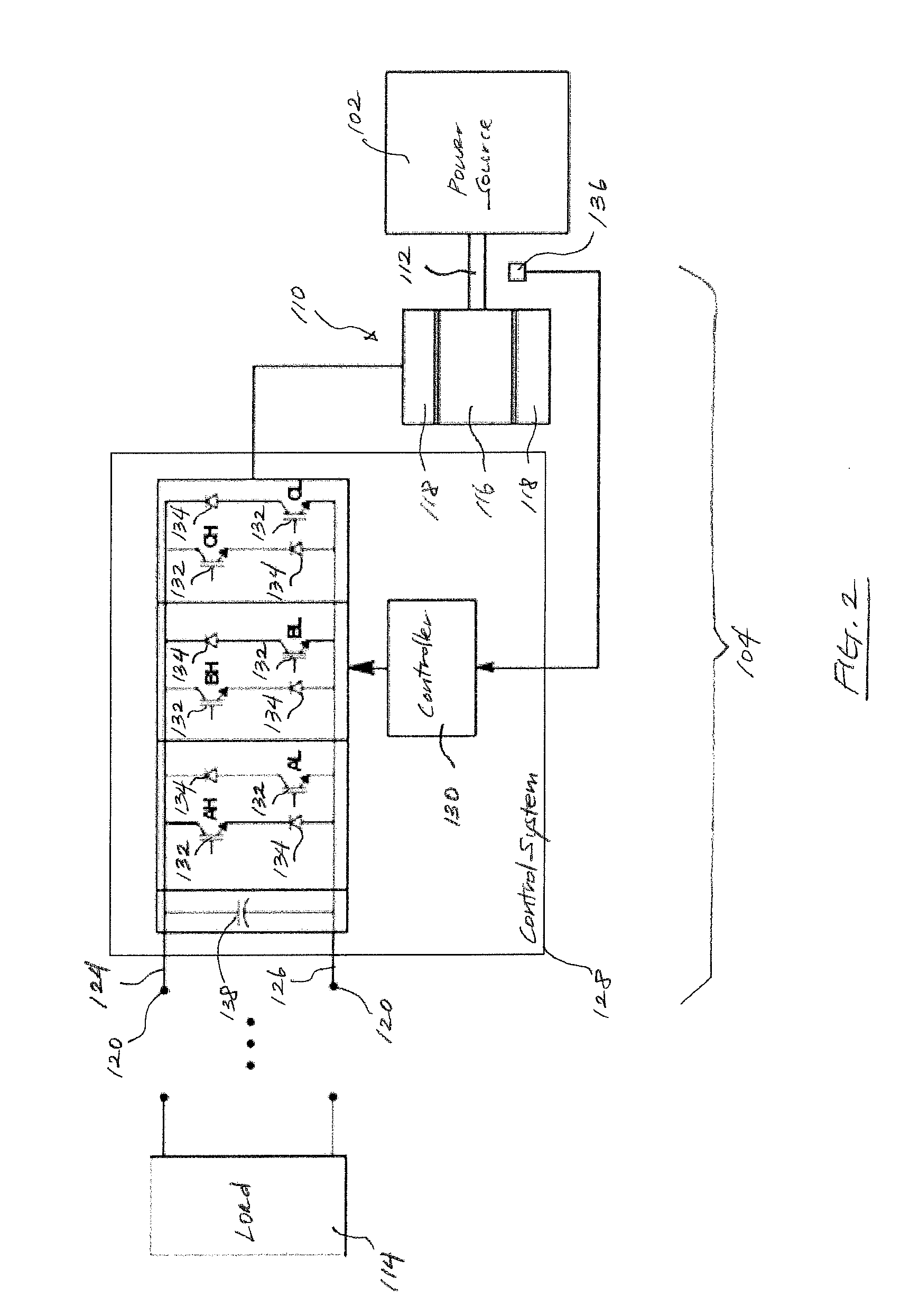
[0020]FIG. 1 diagrammatically illustrates one exemplary embodiment of a machine 100 that may employ electric drive means to generate electrical energy from mechanical energy or vice versa. In the particular embodiment of FIG. 1, for instance, the machine 100 may include a power source 102 coupled to an electric drive 104 for causing movement via a traction device 106. Moreover, the power source 102 may be configured to mechanically transmit power to an electric machine 110, such as a motor / generator, or the like, of the electric drive 104 via a coupling or axially rotating drive shaft 112. Such mobile machines 100 may be used as a work machine for performing a particular type of operation associated with an industry, su...


PUM


Abstract

A control system for compensating a hysteresis band of a switched reluctance (SR) machine having a rotor and a stator is provided. The control system may include a converter circuit and a controller. The converter circuit may be operatively coupled to the stator and include a plurality of switches in selective communication with each phase of the stator. The controller may be in communication with each of the stator and the converter circuit, and configured to monitor at least one phase current of the SR machine relative to a current threshold of the hysteresis band, determine an adjustment value based on a difference between the phase current and the current threshold if the phase current exceeds the current threshold, and compensate the current threshold by the adjustment value.

Description

TECHNICAL FIELD[0001]The present disclosure relates generally to hysteresis-based controls, and more particularly, to systems and methods of compensating hysteresis-based current control in switched reluctance (SR) machines.BACKGROUND[0002]With the growing interest in energy conservation, increasingly more machines, such as mobile industrial work machines or stationary power generation machines, are supplied with electric drive assemblies or systems for operating various tools or functions of the machine. Ongoing developments in electric drives have made it possible for electrically driven machines to effectively match or surpass the performance of mechanically driven machines while requiring significantly less fuel and overall energy. As electric drives become increasingly more commonplace with respect to such machines, the demand for more efficient generators and techniques for controlling same has also increased.[0003]Among the various types of electrically driven machines availa...

Claims


Application Information

Patent Timeline
Patent Type & Authority Applications(United States)
IPC IPC(8): H02P25/08
CPCH02P27/10H02P25/092
Inventor GERDES, JESSEWAI, JACKSONKHALIL, AHMED
Owner CATERPILLAR INC
Why Eureka
Try Eureka