Observer tracking autostereoscopic display

a display device and observer technology, applied in the field of observer tracking autostereoscopic display devices, can solve the problems of limiting the viewing freedom of the display, reducing the spatial resolution of the display, and non-uniform viewing windows, so as to improve the spatial resolution, and improve the spatial resolution

Active Publication Date: 2014-01-23
REALD SPARK LLC
View PDF1 Cites 135 Cited by
  • Summary
  • Abstract
  • Description
  • Claims
  • Application Information

AI Technical Summary

Benefits of technology

[0006]According to the first aspect of the present invention, there is provided a display device for an autostereoscopic display apparatus, the display device comprising: a spatial light modulator comprising an array of pixels; a first lens array and a second lens array, each aligned with the spatial light modulator and operable to direct light from spatially multiplexed sub-arrays of pixels into an array of at least three optical windows in a window plane, the optical windows of the first lens array being spatially offset from the optical windows of the second lens array; and a lens switching arrangement capable of causing the lens arrays to switch between operation in a first mode in which the first lens array operates and the second lens array has substantially no optical effect and a second mode in which the first lens array has substantially no optical effect and the second lens array operates.
[0007]Such display devices may be operated to improve the spatial resolution as compared to an equivalent display device in which a single lens array directs light from spatially multiplexed sub-arrays of pixels into an array of at least three optical windows in a window plane. This is achieved by the provision of the a lens switching arrangement that is capable of causing the lens arrays to switch between operation in a first mode in which the first lens array operates and the second lens array has substantially

Problems solved by technology

However, such displays have reduced spatial resolution compared to the native resolution of the spatial light modulator, and furthermore the structure of the viewing windows is determined by the pixel aperture shape and parallax component imaging function.
Gaps between the pixels, for example, for electrodes, typically produce non-uniform viewin

Method used


Image

  • Observer tracking autostereoscopic display
  • Observer tracking autostereoscopic display
  • Observer tracking autostereoscopic display

Examples


Embodiment Construction

[0078]Time multiplexed autostereoscopic displays can advantageously improve the spatial resolution of an autostereoscopic display by directing light from all of the pixels of a spatial light modulator to a first viewing window in a first time slot, and all of the pixels to a second viewing window in a second time slot. Thus, an observer with eyes arranged to receive light in first and second viewing windows will see a full resolution image across the whole of the display over multiple time slots.

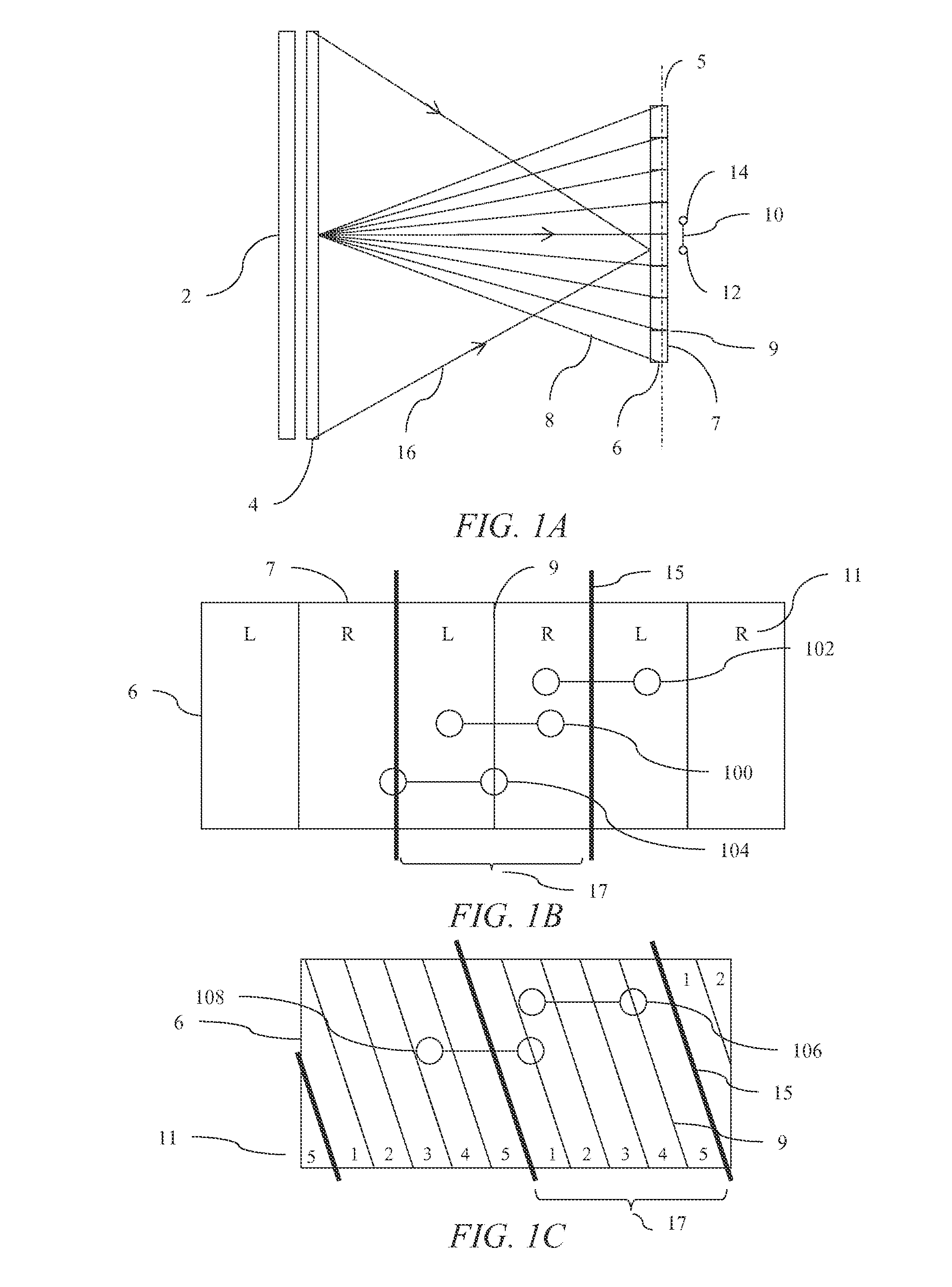
[0079]FIG. 1A is a schematic diagram illustrating a top view of light ray 8, 16 propagation from an autostereoscopic display comprising a spatial light modulator (SLM) 2 comprising an array of pixels arranged in an aperture that has a rectangular shape (as described further below). The SLM 2 is provided with a spatially multiplexing parallax optic 4, such as a parallax barrier or lenticular screen, and arranged to direct rays 8 of light from spatially multiplexed sub-arrays of pixels to an a...


PUM


Abstract

A spatially multiplexed autostereoscopic display is arranged to provide landscape and portrait operation. Multiple optical windows may be provided by spatial and temporal multiplexing techniques. A fast response lens array pair is aligned with a fast response spatial light modulator, and synchronized to provide first and second sets of images with first and second respective directionalities to provide first and second sets of respective optical windows. The first and second sets of optical windows may each comprise two or more optical windows in each viewing lobe. The optical windows may be arranged with an inclination to the vertical of 25 degrees to 65 degrees. An observer tracking system may be arranged to direct left and right eye image data to the left and right eyes of an observer, respectively, for landscape and portrait orientations of the display.

Description

RELATED APPLICATIONS[0001]This application claims priority to U.S. Patent App. No. 61 / 674,735, entitled “Observer tracking autostereoscopic display”, filed Jul. 23, 2012 (RealD Ref: 335000), and to U.S. Patent App. No. 61 / 709,051, entitled “Observer tracking autostereoscopic display”, filed Oct. 12, 2012 (RealD Ref: 335000A), the entireties of which are herein incorporated by reference.TECHNICAL FIELD[0002]This disclosure generally relates to an apparatus for directing light from a spatial light modulator and more specifically relates to autostereoscopic display devices.BACKGROUND[0003]Spatially multiplexed autostereoscopic displays typically align a parallax component such as a lenticular screen or parallax barrier with an array of images arranged as at least first and second sets of pixels on a spatial light modulator, for example an LCD. The parallax component directs light from each of the sets of pixels into different respective directions to provide first and second viewing wi...

Claims


Application Information

Patent Timeline
IPC IPC(8): G02B27/22G02F1/29G02B27/00G02F1/01G02B30/28G02B30/30
CPCG02B27/2214G02F1/01G02F1/29G02B27/0093G02F1/13G02B30/28G02B30/30G02B30/27
Inventor WOODGATE, GRAHAM J.ROBINSON, MICHAEL G.HARROLD, JONATHAN
Owner REALD SPARK LLC
Why Eureka
Try Eureka