
Quasi resonant push-pull converter and control method thereof

Active Publication Date: 2014-01-23
LIAN ZHENG ELECTRONICS (SHENZHEN) CO LTD
View PDF5 Cites 8 Cited by
  • Summary
  • Abstract
  • Description
  • Claims
  • Application Information

AI Technical Summary

Benefits of technology

The invention provides a method for controlling a push-pull converter used in DC-to-DC converters. The converter has a resonant capacitor and is controlled by two power input units and a power output circuit. The power input units supply input to the converter at different times, and a first output capacitor stores the output energy. The method allows for efficient and precise control of the converter with improved performance and reliability.

Problems solved by technology

However, while switching frequency is improved, switching losses will be increased and the problems of inductive turn-off, capacitive turn-on and diodes reverse recovery will be aggravated, which will give rise to reduction of circuit efficiency and increase of electromagnetic interference.
In ZVS-PWM converter and ZCS-PWM converter, a resonant inductor is cascaded in a main power return circuit, so there is a lot circulating energy in the circuit, which inevitably increases closing losses of a circuit.

Method used


Image

  • Quasi resonant push-pull converter and control method thereof
  • Quasi resonant push-pull converter and control method thereof
  • Quasi resonant push-pull converter and control method thereof

Examples


Embodiment Construction

[0028]The exemplary embodiments are introduced now by referring to drawings of the invention. However, the invention can be embodied in many different ways and is not limited to the embodiments described here. Providing those embodiments is to completely disclose the invention in detail and fully express the scope of the invention to those skilled in the art. The terminologies used in the exemplary embodiments of the drawings are not definitions to the invention. In the drawings, identical reference sign is used for identical unit / element.

[0029]Unless otherwise stated, the “one”, “a”, “said” and “the” also refer to plural forms. Furthermore, it should be understood that the terminologies “comprise”, “include” and / or “contain” in the description designate some features, objects, procedures, operations, units and / or elements, but not exclude one or more features, objects, procedures, operations, units and / or elements and / or groups composed of them. It should be known that when a unit ...


PUM


Abstract

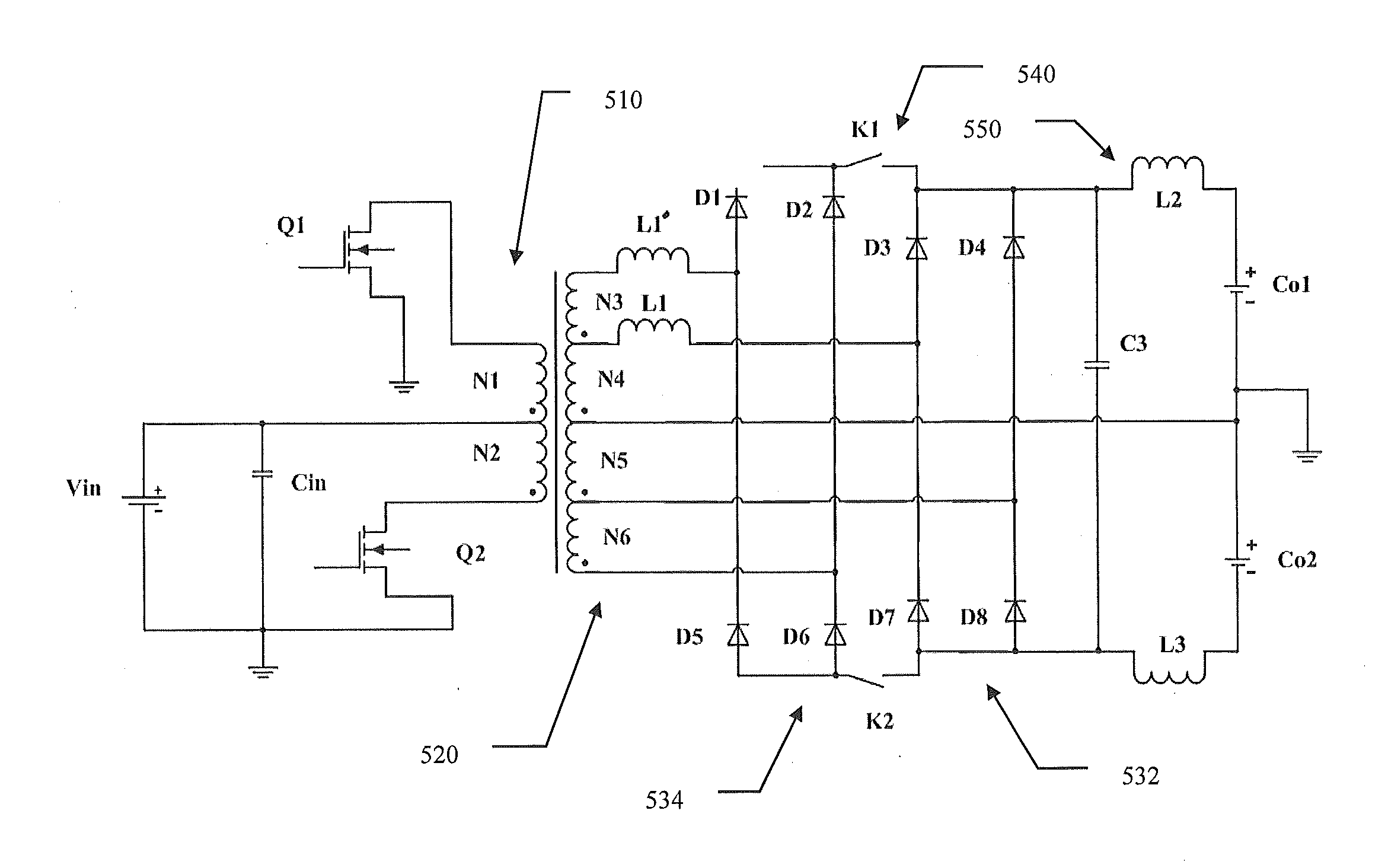
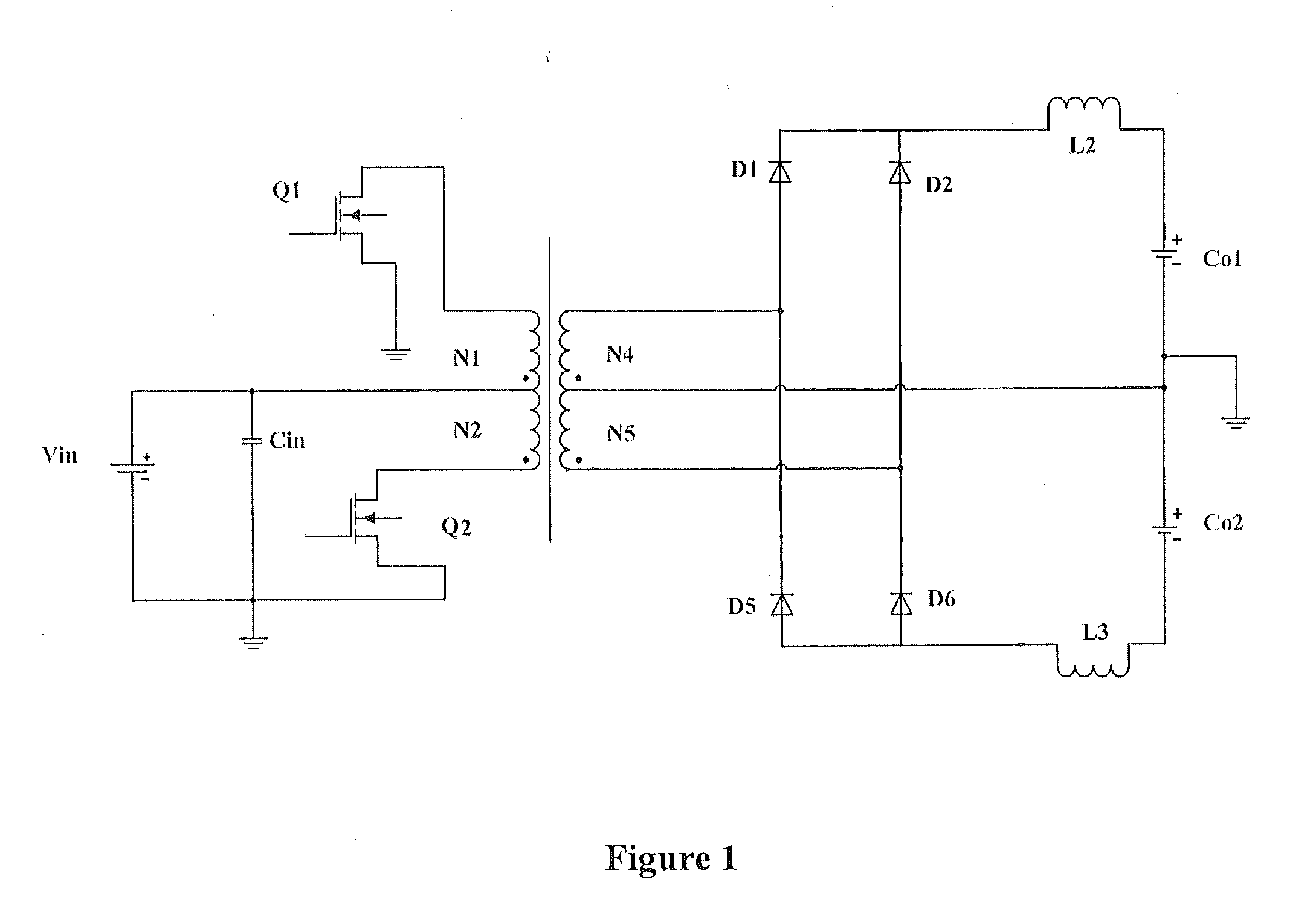
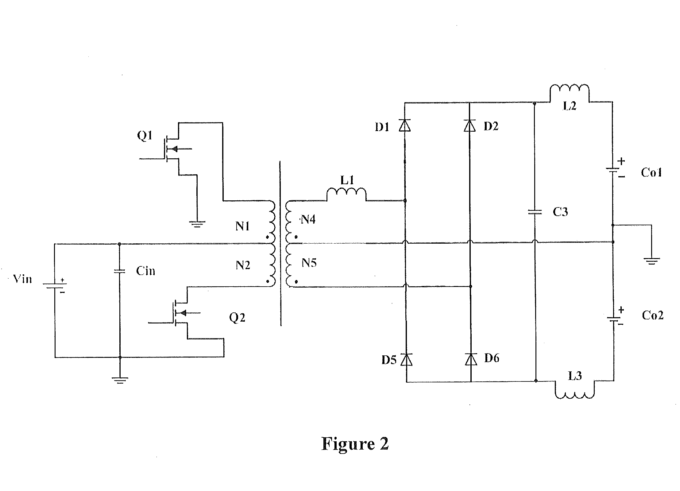
The invention relates to a quasi-resonant push-pull converter and the method for controlling the same, said push-pull converter comprising: a direct current (DC) input power supply configured to supply DC input for the converter; a first power input unit and a second power input unit, connected to said DC input power supply, respectively and configured to supply input for the converter in different periods, comprising a first power switching tube and a second power switching tube, a first primary winding and a second primary winding; a power output circuit, configured to supply output of the converter, comprising secondary windings and full-bridge rectification circuits; a first output capacitor and a second output capacitor connected to said power output circuit and configured to store DC electric energy output by the power output circuit in which a resonant element is arranged to achieve a quasi-resonant switching circuit through voltage feedback; and a switching circuit being controlled through voltage feedback, whereby turns ratio of the primary windings and the secondary windings of the push-pull converter is controlled.

Description

FIELD OF THE INVENTION[0001]This invention relates to the field of power electronics technology, and more particularly, relates to a quasi-resonant push-pull converter and the method for controlling the same.BACKGROUND OF THE INVENTION[0002]Currently, the development in power electronics technology requires electronic products to be smaller and lighter, and makes a higher requirement on efficiency and electromagnetic compatibility. In a power electronics device, a filter inductor, a capacitor and a transformer account for a large proportion, so taking measures to reduce the size and weight of those components is a major means for the concept of being smaller and lighter. Improving switching frequency can accordingly improve cut-off frequency of a filter, and thus comparatively smaller inductors and capacitors can be chosen to reduce the size and weight of a filter. Improving switching frequency can reduce the size and weight of a transformer similarly.[0003]However, while switching ...

Claims


Application Information

Patent Timeline
IPC IPC(8): H02M3/337H02M1/00
CPCH02M3/3376H02M3/3372Y02B70/10H02M1/0058
Inventor HE, ZHIFENGYANG, YUCHENG
Owner LIAN ZHENG ELECTRONICS (SHENZHEN) CO LTD
Learn More