
Plug connector

a technology of plug and connector, applied in the direction of coupling device connection, coupling protective earth/shielding arrangement, electric discharge lamps, etc., can solve the problems of affecting the overall connector structure, reducing the capability of devices, equipment or systems, and thus hindering the function of the connector assembly, so as to simplify the assembly process and stabilize the overall connector structure

Active Publication Date: 2014-01-23
ADVANCED CONNECTEK INC
View PDF14 Cites 27 Cited by
  • Summary
  • Abstract
  • Description
  • Claims
  • Application Information

AI Technical Summary

Benefits of technology

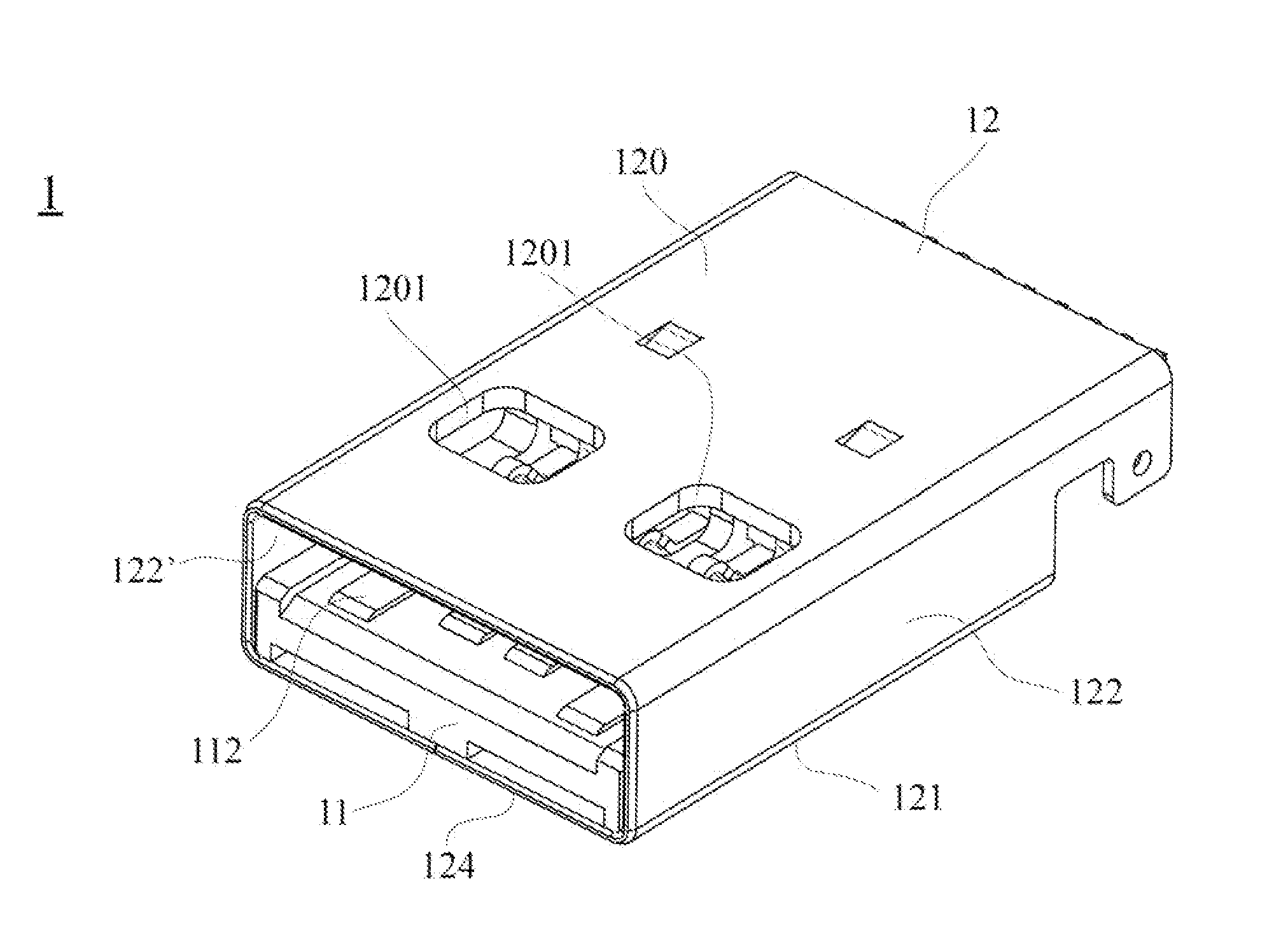
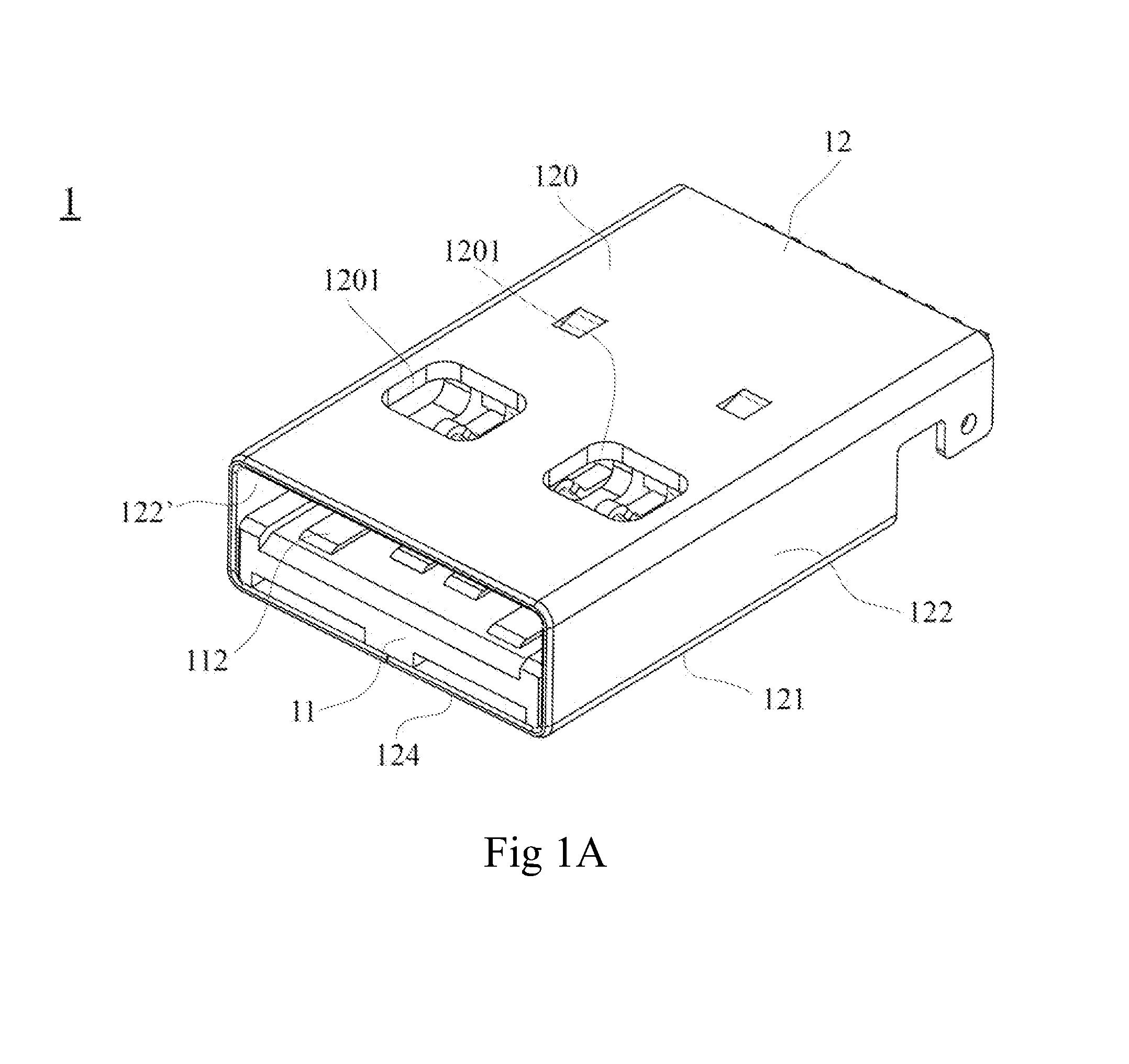
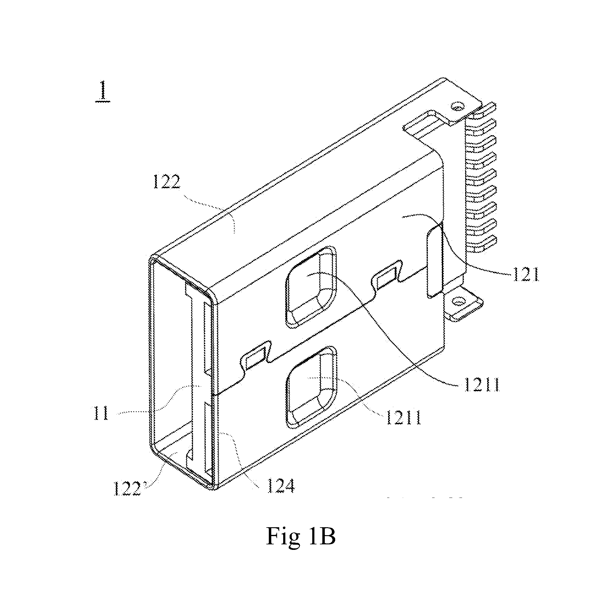
The present invention aims to improve the contact between the metal shell and the resilient portion of the receptacle connector. By using a stamping process on metal material to create recesses or protrusions, the plug connector can better prevent EMI, crosstalk, and dust and debris. This modification ensures stable insertion and extraction strength after frequent uses and extends the lifespan of the plug connector. Additionally, the invention provides a simple and unified solution to address EMI issues in the metal shell with holes showing in prior art. Overall, the invention simplifies the assembly process and unifies connector elements while solving EMI issues.

Problems solved by technology

While in application of the connector, EMI (electromagnetic interference), an electromagnetic phenomenon that will affect and eventually reduce the capability of the devices, equipment or systems.
However, since there is no sheltering device to prevent influence from EMI, when the plug is to connect to the receptacle connector, EMI becomes the biggest concern for function stability.
Moreover, the two holes of the metal shell easily trap dust and debris of some kind and hence the function of the connector assembly is thus hindered.

Method used


Image

  • Plug connector
  • Plug connector
  • Plug connector

Examples


first embodiment

[0060]Moreover, except for the modification of the top plate 120 of the metal shell 12 and the resilient plates 21, 21′ of the receptacle connector 2 by using the same metal substance stamped to form at least a recess or protrusion for achieving excellent electromagnetic shielding function, EMI or crosstalk could also be improved by widening or minimizing the first conductive terminal 112 or the second conductive terminal 114 partially to stabilize the connection. Firstly please refer to FIG. 17 which is a bottom perspective view of the first conductive terminals 112 and the second conductive terminals 114 according to the present invention. The first conductive terminals 112 comprise a first pair of signal terminals 1124, an electrical terminal 1125 and a power ground terminal 1126. The first pair of the signal terminals 1124 parallel are attached to the first terminal receiving space 1153 of the first body 115, and the first contact portion 1120′ is exposed to the top surface 1151...

third embodiment

[0065]Accordingly the first, second and the present invention avoid crosstalk interference induced by the first pair of the signal terminal 1124 (D+ / D−) in the second pair of the signal terminals 1145 (SSTX+ / SSTX−) and the third pair of the signal terminals 1146 (SSRX+ / SSRX−). These make the signal transmission more stable than prior art does.


PUM


Abstract

A plug connector is for connecting to a receptacle connector. The receptacle connector comprises two resilient plates. The plug connector has an insulating housing and a metal shell. The insulating housing includes a tongue portion and a base portion for accommodating and connecting the terminals. The metal shell has a top plate, bottom plate, and two side plates. Multiple recesses, protrusions or elongated recesses are selectively formed on at least one of the top plate, the bottom plate for connecting the resilient plates. These can avoid electromagnetic interference, dusts or any external substances from attaching to the insulating house and also ensure a high quality of the insertion force and the extraction force after frequent uses.

Description

BACKGROUND OF THE INVENTION[0001]1. Field of the Invention[0002]The present invention relates to a plug connector, and more particularly to a plug connector which can avoid EMI, dusts or any external substances from attaching to the metal shell and also ensure stable insertion and extraction strength after frequent uses.[0003]2. Description of the Prior Art[0004]USB (Universal Serial Bus) connector is a type of connector that is widely used for the connection of electronic devices and related peripheral devices because of the advantages of easy connection to a device, plug-and-play and high efficiency of data transmission etc. Due to the upgrade of USB connectors, the ones with faster and more stable transmission function are needed.[0005]Following the demands for transmission speed and storing capacity, the goal in industry standard is to achieve a transmission speed 10 times faster than the current speed. Adoption of the design structure of the current USB, one can improve the cur...

Claims


Application Information

Patent Timeline
Patent Type & Authority Applications(United States)
IPC IPC(8): H01R13/516
CPCH01R13/516H01R13/658H01R12/716H01R12/712H01R13/6594H01R12/00
Inventor DONG, FEI-WUWAN, WEILIN, SHENG-CHANDUAN, SHU-LIN
Owner ADVANCED CONNECTEK INC
Learn More