
Caster device with a directional mechanism

Active Publication Date: 2014-01-30
WONDERLAND SWITZERLAND AG
View PDF8 Cites 4 Cited by
  • Summary
  • Abstract
  • Description
  • Claims
  • Application Information

AI Technical Summary

Benefits of technology

The purpose of this invention is to create a caster device that can change from a universal state to an orientation state effectively. This change is designed to solve problems that previously existed with the caster device.

Problems solved by technology

However, it is difficult to turn the hand propelled vehicle due to the fixed moving direction of the directional wheel device.
However, flexibility of the hand propelled vehicle with the universal wheel device sacrifices stability and directionality.
However, because the directional pin is disposed on the directional mechanism, and the directional mechanism is near the protecting cover of the caster, the directional pin cannot be inserted into the corresponding hole pit rapidly for locking the caster bracket to ensure the directional function.
Moreover, a directional effect of this directional mechanism is poor, so that the castor is easily turned from the directional state to a universal state as the castor is turned.

Method used


Image

  • Caster device with a directional mechanism
  • Caster device with a directional mechanism
  • Caster device with a directional mechanism

Examples


Embodiment Construction

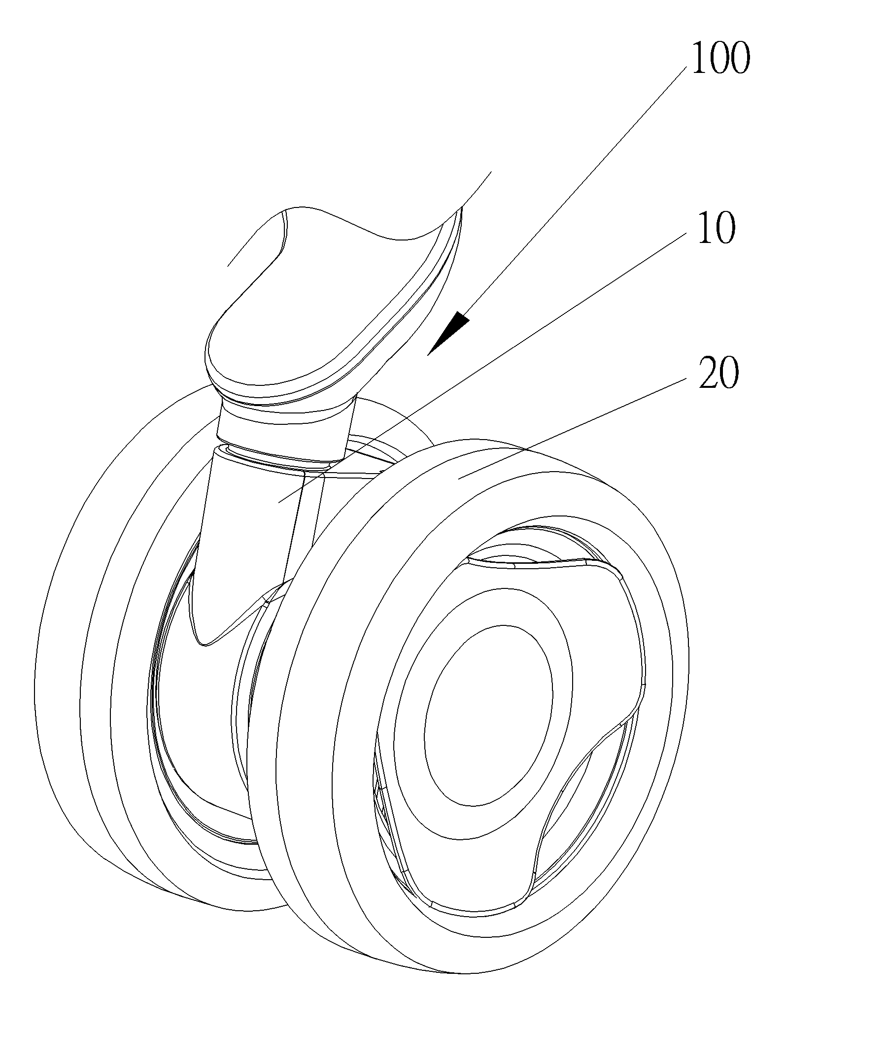
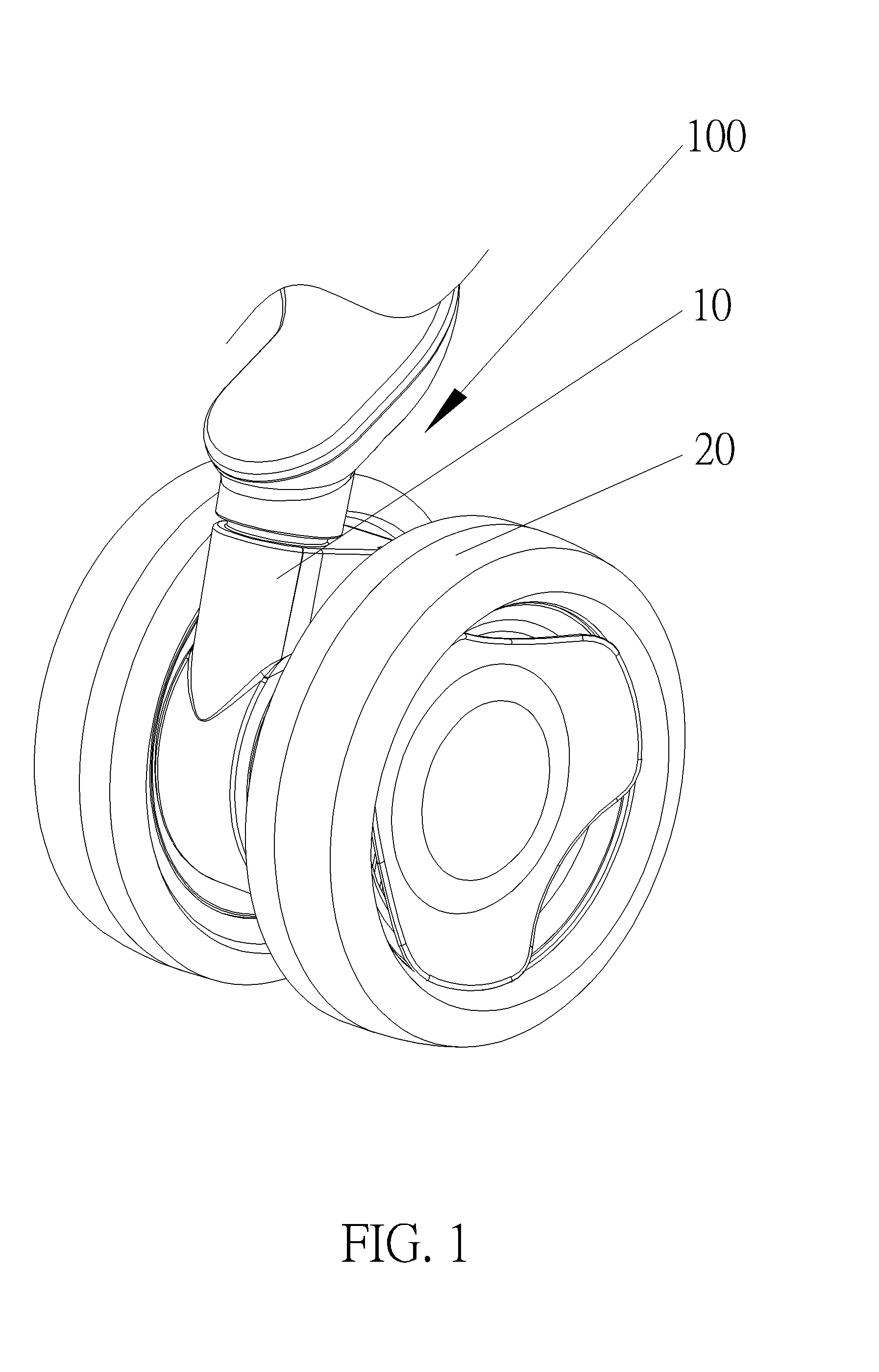
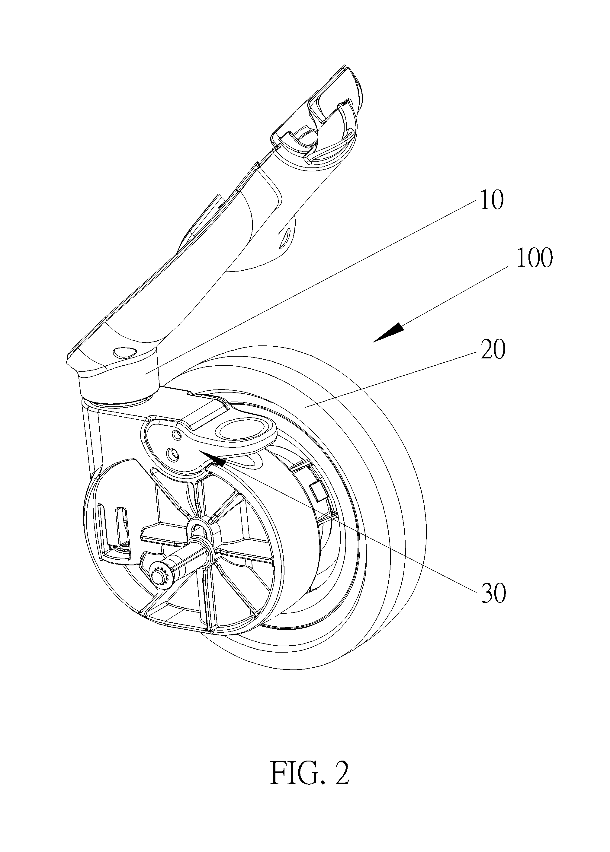
[0040]Please refer to FIG. 1 to FIG. 3. FIG. 1 is a diagram of a caster device 100 according to an embodiment of the present invention. FIG. 2 is a partial diagram of the caster device 100 according to the embodiment of the present invention. FIG. 3 is an exploded diagram of the caster device 100 shown in FIG. 2 according to the embodiment of the present invention. The caster device 100 includes a column 10, a wheel module 20 and a directional mechanism 30. The wheel module 20 can include two wheels or a single wheel. In this embodiment, the wheel module 20 includes two wheels. The wheel module 20 is pivoted on the column 10, so that the caster device 100 can be a universal caster. The directional mechanism 30 includes a directional component 33 movably disposed inside the wheel module 20 and detachably engaged with the column 10. A moving direction of the directional component 33 is intersected with a pivoting axis of the wheel module 20. Because the moving direction of the directi...


PUM


Abstract

The present invention discloses a caster device comprising a column, a wheel module and a directional mechanism. The wheel module is pivoted on the column. The directional mechanism includes a directional component movably disposed inside the wheel module and detachably engaged with the column. A moving direction of the directional component is intersected with a pivoting axis of the wheel module. Because the moving direction of the directional component of the present invention is intersected with the pivoting axis of the wheel module, the column is locked well, so as to result in a better orientation effect by using the directional mechanism. The directional component is movably disposed inside the wheel module, so that the directional component is intersected with the pivoting axis of the wheel module rapidly, so as to increase an operating efficiency for orientation.

Description

BACKGROUND OF THE INVENTION[0001]1. Field of the Invention[0002]The present invention relates to a caster device, and more specifically, to a caster device with a directional mechanism.[0003]2. Description of the Prior Art[0004]In modern life, a hand propelled vehicle with a wheel device, such as a stroller, a supermarket cart, a luggage case or an ambulance bed, is widely utilized. The wheel devices for the hand propelled vehicle are generally divided into a directional wheel device and a universal wheel device, based on purposes and requirements of the vehicles. In general, the hand propelled vehicle with the directional wheel device only can be moved in a straight line, so as to ensure stability and directionality of the hand propelled vehicle. However, it is difficult to turn the hand propelled vehicle due to the fixed moving direction of the directional wheel device. As for the hand propelled vehicle with the universal wheel device, since the wheel may rotate in 360 degrees rot...

Claims


Application Information

Patent Timeline
IPC IPC(8): B60B33/02
CPCB60B33/023B60B5/02B60B33/025B60Y2200/83B60B33/02
Inventor ZHU, WANQUAN
Owner WONDERLAND SWITZERLAND AG
Features
  • Generate Ideas
  • Intellectual Property
  • Life Sciences
  • Materials
  • Tech Scout
  • Unparalleled Data Quality
  • Higher Quality Content
  • 60% Fewer Hallucinations
Learn More