Security wrap

a security wrap and wrap technology, applied in the direction of printed circuit aspects, instruments, internal/peripheral component protection, etc., can solve the problems of prior art security wrap breach, alarm circuit activation, connection broken, etc., and achieve the effect of reducing the probability of pattern repetition

Active Publication Date: 2014-01-30
JOHNSON ELECTRIC SA
View PDF4 Cites 36 Cited by
  • Summary
  • Abstract
  • Description
  • Claims
  • Application Information

AI Technical Summary

Benefits of technology

[0012]Preferably, the pattern of said conductive path is selected from the plurality of predetermined patterns in accordance with an algorithm to reduce the probability of pattern repetition.
[0029]Preferably, the first pattern of said first conductive track and the second pattern of said second conductive track are selected from the plurality of predetermined patterns in accordance with an algorithm to reduce the probability of pattern repetition in a security wrap production process.

Problems solved by technology

In use, when unauthorized physical entry is attempted by removing the security wrap, the connection is broken and the alarm circuit is activated.
Prior art security wraps may be breached by drilling a hole through the security wrap to access the circuit beneath.
Commonly this is determined using some form of x-ray inspection, which is expensive or by disassembling a sample product, which is destructive.
If a thief can determine how to hack into one device with a security wrap and determine how to bypass the security screen all similar devices are now compromised as each model uses the same security wrap which is fixed to the same PCB within very tight tolerances to ensure good manufacturability and security.

Method used


Image

  • Security wrap
  • Security wrap
  • Security wrap

Examples


Embodiment Construction

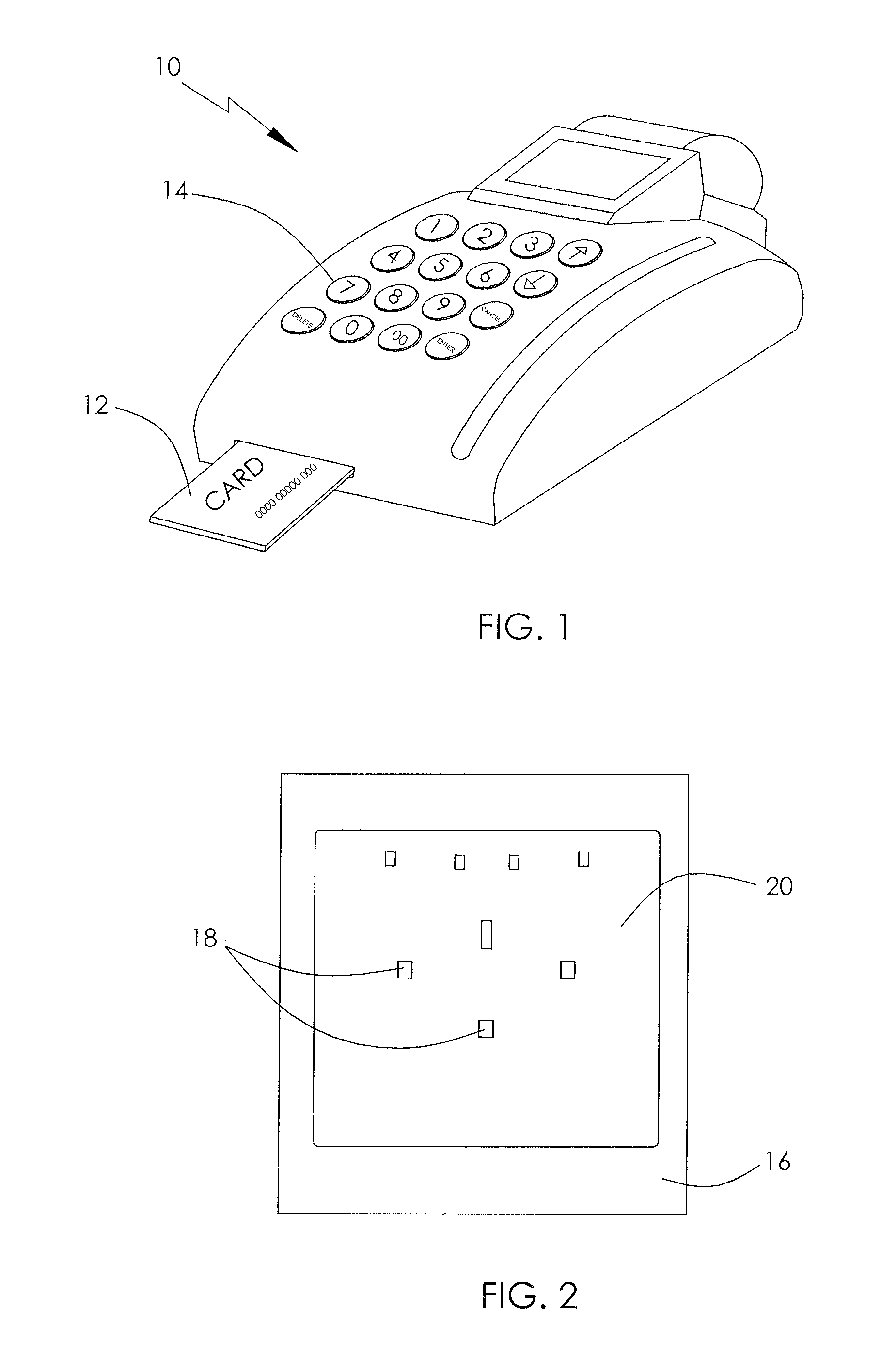
[0040]FIG. 1 illustrates an electronic device, by way of example, in the form of a point of sale (POS) device 10. The POS device 10 is arranged to read details from a card 12, such as a credit card and has a key pad 14 for entering information and giving instructions to the PUS device 10. A security wrap is used to protect the data stored in the memory of the FOS device 10, generally some form of a memory chip. If unprotected, a perpetrator may access the contents of the memory in the POS device 10.

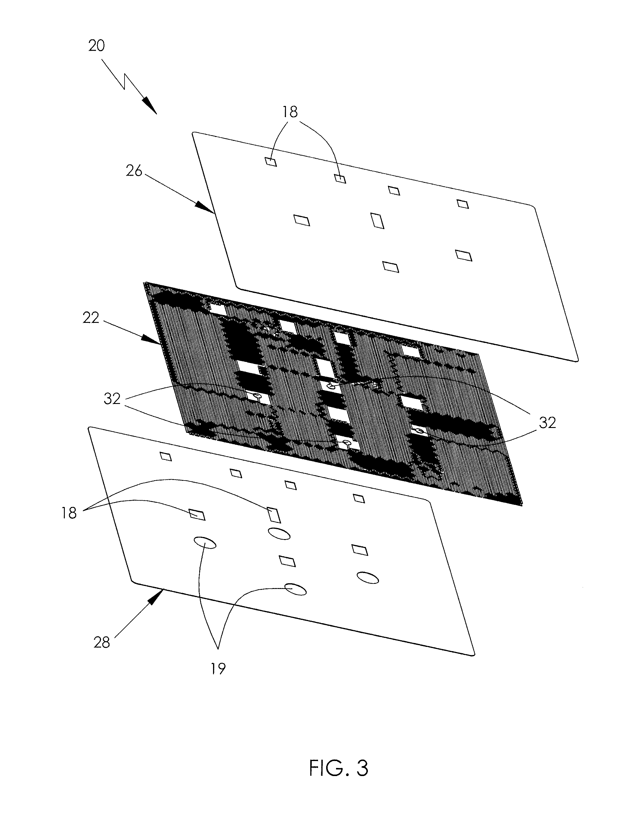
[0041]A PCB 16 of device 10 is shown in FIG. 2 with a security wrap 20 fitted thereon. Security wrap 20 appears as a flexible sheet overlaying PCB 16. In accordance with a preferred embodiment of the present invention, a substrate of the security wrap 20 is opaque so as to hide a security screen (not shown in FIG. 2) and the underlying circuitry on PCB 16. Holes 18 in security wrap 20 and PCB 16 facilitate the mounting of the PCB 16 to a housing of device 10.

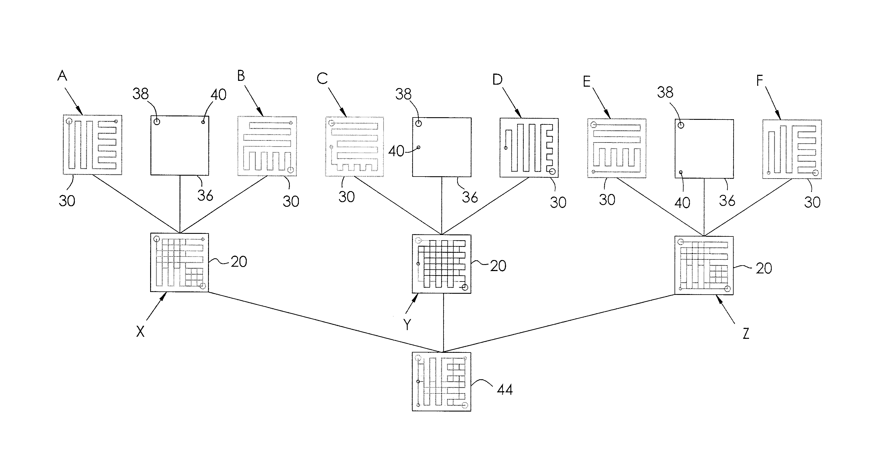
[0042]FIG. 3 illustrates the c...


PUM


Abstract

A security wrap (20) for protecting an electronic component (16) includes a substrate (26) having a first side and a second side opposite to each other. A conductive path (22) is disposed over the first side of the substrate (26) and has first and second ends coupled to the electronic component (16), and a pattern selected from a plurality of predetermined patterns. A layer of adhesive (28) is over the first side of the substrate (26) and bonds the first side of the substrate (26) to the electronic component (16) with the conductive path (22) sandwiched there between.

Description

CROSS REFERENCE TO RELATED APPLICATIONS[0001]This non-provisional patent application claims priority under 35 §119(a) from Patent Application No. 1213445.8 filed in United Kingdom on Jul. 27, 2012.FIELD OF THE INVENTION[0002]This invention relates to a security device for an electronic circuit board and in particular, to a flexible security overlay having a randomly assigned security screen pattern.BACKGROUND OF THE INVENTION[0003]Protecting electronic circuits from unauthorized access is an important consideration when designing apparatus that use electronic circuits that have or may have sensitive and / or confidential information. For example, point of sale (POS) devices collect confidential information about credit cards or bank account details when a purchase is being made.[0004]The protection of such devices can be achieved by a security device commonly referred to as a security wrap. The security wrap forms a part of the device's security system and identifies an attempt to phy...

Claims


Application Information

Patent Timeline
Patent Type & Authority Applications(United States)
IPC IPC(8): H05K1/02
CPCH05K1/0275G08B13/128H05K2201/09263G06F21/87G06F21/86G09F3/0329H01L23/576G08B13/242
Inventor SALLE, VINCENT DANIEL JEANWARD, DOMINIC JOHNEDMONDS, MARTIN WALLACEZHANG, LIBING
Owner JOHNSON ELECTRIC SA
Why Eureka
Try Eureka