Method for dynamic feed pressure adjustment

a feed pressure adjustment and dynamic technology, applied in the field of dynamic feed pressure adjustment, can solve the problems of deformation of wires, erratic welding arcs, and rollers , achieve the effect of increasing the tension

Inactive Publication Date: 2014-01-30
LINCOLN GLOBAL INC
View PDF5 Cites 20 Cited by
  • Summary
  • Abstract
  • Description
  • Claims
  • Application Information

AI Technical Summary

Benefits of technology

[0013]The method above further includes calculating the driven speed of the wire by taking into account the rotational speed and the diameter of at least one of the pair of rollers and increasing the tension between the

Problems solved by technology

Unfortunately, if the tension between rollers 14 is set too high, the rollers 14 will deform the wire 35 as it passes therethrough.
On the other hand, if the

Method used


Image

  • Method for dynamic feed pressure adjustment
  • Method for dynamic feed pressure adjustment
  • Method for dynamic feed pressure adjustment

Examples


Embodiment Construction

[0028]The best mode for carrying out the invention will now be described for the purposes of illustrating the best mode known to the applicant at the time of the filing of this patent application. The examples and figures are illustrative only and not meant to limit the invention, which is measured by the scope and spirit of the claims.

[0029]The invention relates to a an automatic feed adjuster is utilized to provide optimized wire feeding and welding.

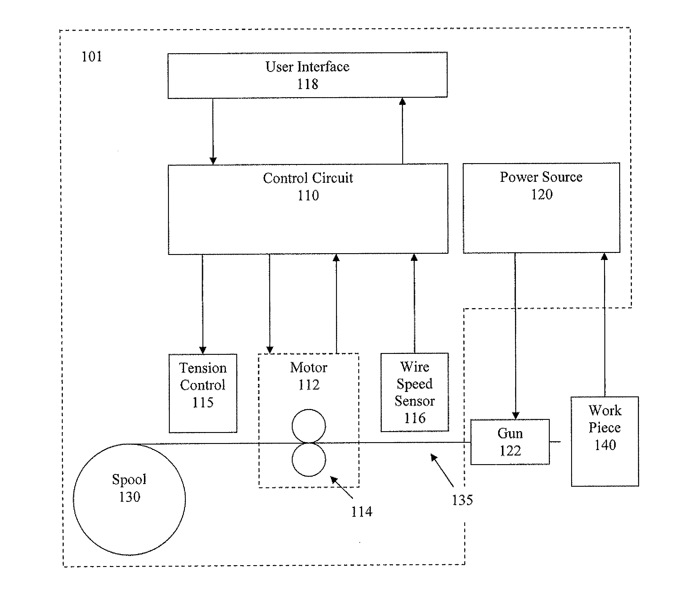
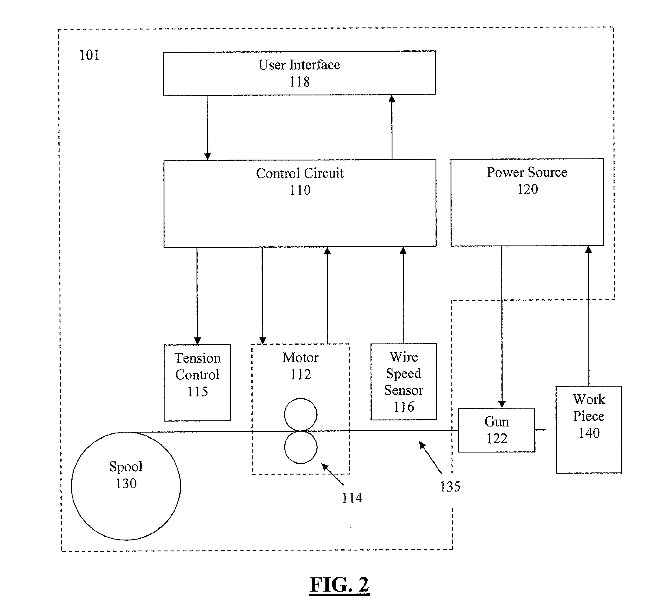
[0030]More specifically, as shown in FIG. 2, welding system 101 includes control circuit 110, power source 120, motor 112, tension control 115, wire speed sensor 116, user / data interface 118, and spool 130. Spool 130 contains wire 135 spooled thereon. Motor 112 drives opposing rollers 114 to take up wire 135 from spool 130 and send it to gun 122. The operator utilizes gun 122 to form a weld on workpiece 140. As the weld is formed on workpiece 140, wire 135 is consumed, and is replaced by motor 112.

[0031]User / data interface 118 provides...


PUM

PropertyMeasurementUnit
Diameteraaaaaaaaaa
Speedaaaaaaaaaa
Tensionaaaaaaaaaa

Abstract

The invention relates to devices, systems, and methods for automatic feed adjustment during welding operations using a pressure measuring device and a welding wire knowledge database to adjust tension between at least one pair of wire feed rolls, at least one of which is a drive roll.

Description

CROSS-REFERENCE TO RELATED APPLICATIONS[0001]This application is a continuation-in-part application of pending U.S. patent application Ser. No. 11 / 755,821 filed 31 May 2007, and claims priority thereto and fully incorporates by reference the same.TECHNICAL FIELD[0002]The invention described herein pertains generally to devices, systems, and methods for automatic feed adjustment during welding operations.BACKGROUND OF THE INVENTION[0003]In the related art, there are various types of welding processes, including processes which utilize a continuous wire feed as a welding electrode.[0004]A diagrammatical representation of such a related art continuous wire feed welding process is illustrated in FIG. 1, which illustrates a welding system 1 which includes control circuit 10, power source 20, motor 12, and spool 30. Spool 30 contains wire 35 spooled thereon. Motor 12 drives opposing rollers 14 to take up wire 35 from spool 30 and send it to gun 22. The operator utilizes gun 22 to form a w...

Claims


Application Information

Patent Timeline
IPC IPC(8): B23K9/12B23K9/095
CPCB23K9/0956B23K9/124B23K9/1336B23K9/173
Inventor CHANTRY, BRUCE JOHN
Owner LINCOLN GLOBAL INC
Why Eureka
Try Eureka