
Light source module

a light source module and light source technology, applied in the field of light source modules, can solve the problems of poor uniformity and light utilization efficiency of plane light sources, inability to directly achieve ccfl, and inefficient utilization of light reflected by the reflective cover, so as to enhance the light emission uniformity and enhance the light emission efficiency of the light source module

Inactive Publication Date: 2014-01-30
DONGGUAN MASSTOP LIQUID CRYSTAL DISPLAY +1
View PDF0 Cites 7 Cited by
  • Summary
  • Abstract
  • Description
  • Claims
  • Application Information

AI Technical Summary

Benefits of technology

The light source module described in this patent increases the efficiency of emitting light using a reflector and a light guiding element. The reflector is positioned opposite the light incident surface, and the light emitted from the light emitting element is reflected and evenly emitted from the light emitting surface. The light emitting surface can be divided into sections to enhance the efficiency of light emission. The light guiding element can be designed with microstructures to reduce uneven brightness and can be combined with optical films for better light emitting quality. The light source module can meet the required anti-glare specification for illumination applications.

Problems solved by technology

Nevertheless, the light reflected by the reflective cover can not be efficiently utilized.
In addition, the CCFL is a linear light emitting element so that a plane light source can not be directly achieved by using the CCFL.
However, the uniformity and the light utilization efficiency of such plane light source are often poor.
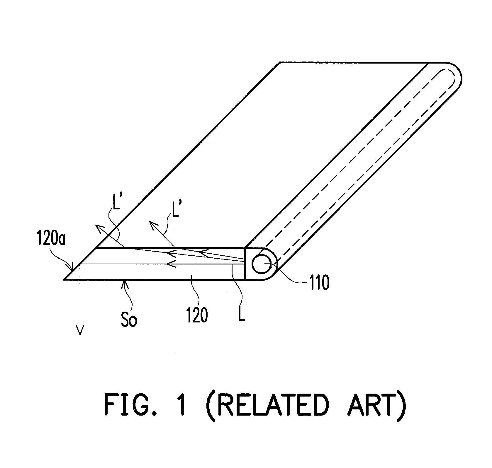
However, a portion of the light L′ is emitted from the surface outside the light emitting surface So, which causes poor light utilization efficiency of the light source module.
The glare effect is resulted from an unfavorable brightness distribution or an extreme contrast between the object and the background, which causes poor visibility of the object and uncomfortable feeling of the user.

Method used


Image

  • Light source module
  • Light source module
  • Light source module

Examples


first embodiment

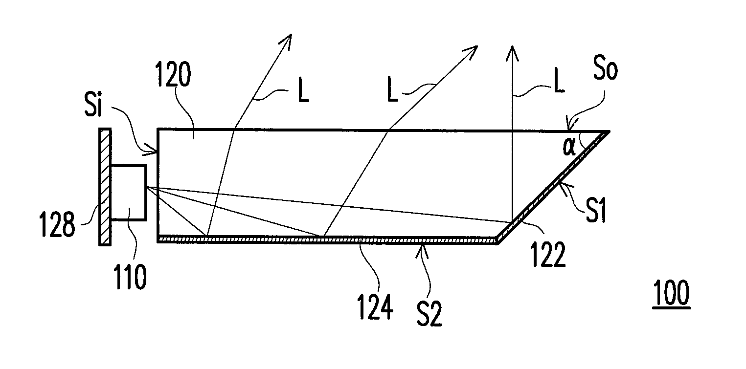
[0029]FIG. 2 is a schematic cross-sectional view of a light source module according to the invention. Referring to FIG. 2, the light source module 100 according to the present embodiment includes a light emitting element 110, a light guiding element 120, a reflective layer 122 and a reflective layer 124. In the present embodiment, the light emitting element 110 can, for example, be a light emitting diode (LED). However, the invention is not limited thereto. In an alternate embodiment, the CCFL or other light emitting element can replace the LED as the light emitting element 110 of the present embodiment.

[0030]The light guiding element 120 has a light incident surface Si, a light emitting surface So, a first surface S1, and a second surface S2. The light emitting element 110 faces to the light incident surface Si. The light emitting surface So is connected to the light incident surface Si. The first surface S1 is connected to the light emitting surface So and opposite to the light in...

second embodiment

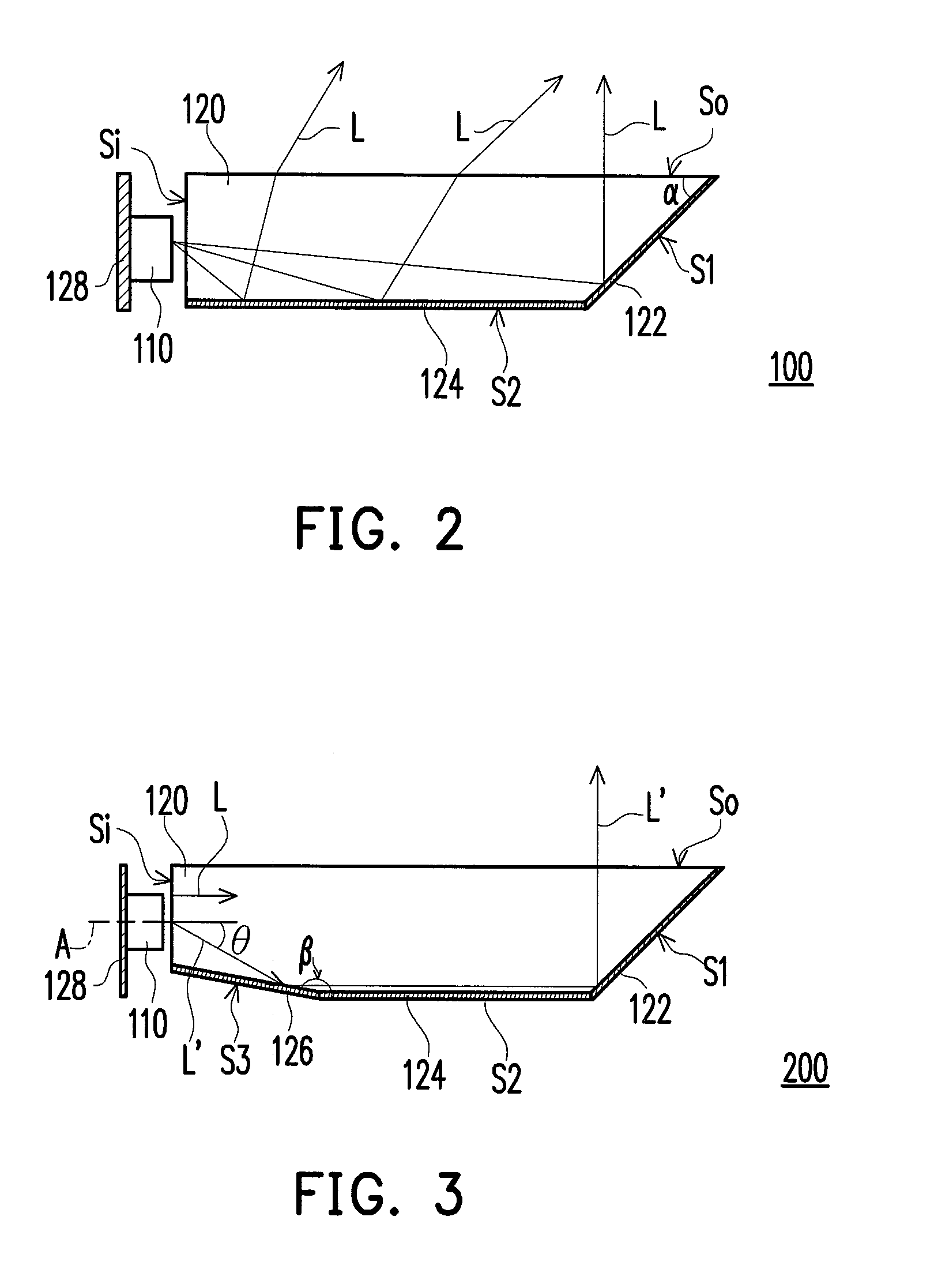
[0034]FIG. 3 is a schematic view of a light source module according to the invention. Referring to FIG. 3, the light source module 200 has a design mainly similar to that of the light source module 100. In the present embodiment, the light guiding element 120 is formed by mold-extrusion process. The light guiding element 120 is not liable to have a V-cut light incident structures on the light incident surface Si for enhancing the light uniformity when the V-cut light incident structure substantially extends in a direction perpendicular to the extrusion direction of the mold-extrusion process. Therefore, the light guiding element 120 of the light source module 200 can further include a third surface S2 connected between the light incident surface S1 and the second surface S2 and an obtuse angle β is included by the third surface S3 and the second surface S2. The obtuse angle β can be from 165° to 170°. In other words, the third surface S3 is a slightly inclined surface configured adj...

third embodiment

[0036]FIG. 4 is a schematic view of a light source module according to the invention. Referring to FIG. 4, the light source module 300 has a design mainly similar to that of the light source module 200. Nevertheless, in the light source module 300 of the present embodiment, the light incident surface Si can selectively have a first concave H1 suitable for accommodating the light emitting element 110. The light emitting element 110 is accommodated in the first concave H1 of the light incident surface Si so that the light L emitted from the light emitting element 110 is efficiently introduced into the light guiding element 120 from the light incident surface Si.

[0037]FIG. 5 is a schematic view of a light source module according to the fourth embodiment of the invention. Referring to FIG. 5, the light source module 500 has a design mainly similar to that of the light source module 100 in the first embodiment. However, the light source module 400 in the present embodiment further includ...


PUM


Abstract

A light source module including a light emitting element and a light guiding element is provided. The light guiding element has a light incident surface, a light emitting surface, a first surface, a second surface, a first reflective layer, and a second reflective layer. The light emitting element faces to the light incident surface. The light incident surface is connected to the light emitting surface. The first surface is connected to the light emitting surface and opposite to the light incident surface. The first surface is non-parallel to the light incident surface. The second surface is connected to the first surface and opposite to the light emitting surface. The first reflective layer is disposed on the first surface. The second reflective layer is disposed on the second surface.

Description

CROSS-REFERENCE TO RELATED APPLICATION[0001]This application claims the priority benefit of U.S. provisional application Ser. No. 61 / 675,329, filed on Jul. 25, 2012. The entirety of the above-mentioned patent application is hereby incorporated by reference herein and made a part of this specification.BACKGROUND OF THE INVENTION[0002]1. Field of the Invention[0003]The present invention relates to a light source module, and more particularly to a light source module including a reflective layer.[0004]2. Description of Related Art[0005]A conventional illumination device uses a cold-cathode fluorescent lamps (CCFL) as the light emitting element. The CCFL provides a non-directional light source so that the light emitted thereby irradiates toward various directions. Thus, a reflective cover configured beside the CCFL is usually required to reflective the light emitted from the CCFL toward certain irradiation region. Nevertheless, the light reflected by the reflective cover can not be effi...

Claims


Application Information

Patent Timeline
Patent Type & Authority Applications(United States)
IPC IPC(8): F21V8/00
CPCG02B6/0021G02B6/0038G02B6/0046G02B6/0055G02B6/009
Inventor YE, ZHI-TINGLIN, MING-CHUANHUANG, KUO-JUI
Owner DONGGUAN MASSTOP LIQUID CRYSTAL DISPLAY
Learn More