Optical fiber and optical transmission system

a technology of optical fiber and optical transmission system, applied in the direction of optical elements, cladded optical fibre, instruments, etc., can solve the problem of insufficient transmission capacity

Active Publication Date: 2014-01-30
FURUKAWA ELECTRIC CO LTD
View PDF1 Cites 10 Cited by
  • Summary
  • Abstract
  • Description
  • Claims
  • Application Information

AI Technical Summary

Benefits of technology

[0006]It is an object of the present invention to at lea...

Problems solved by technology

With the recent dramatic increase in the Internet traffic, it is ...

Method used


Image

  • Optical fiber and optical transmission system
  • Optical fiber and optical transmission system
  • Optical fiber and optical transmission system

Examples


first embodiment

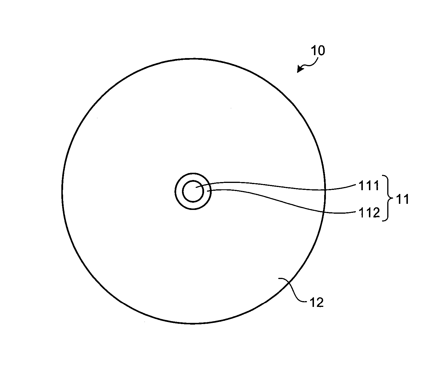
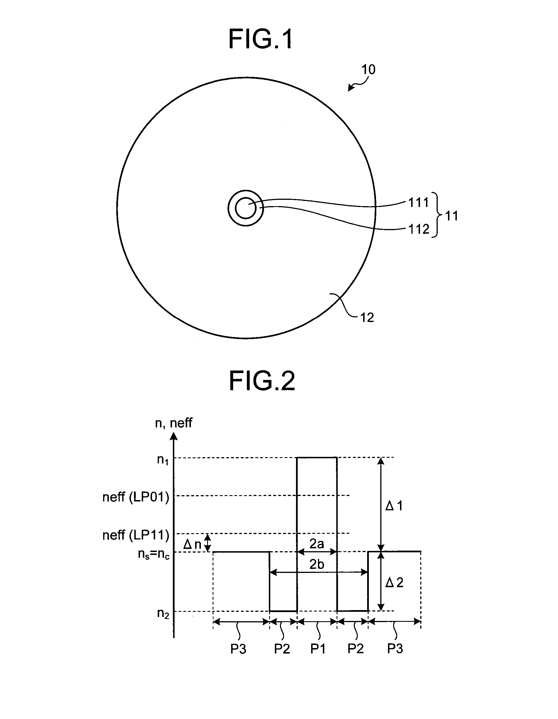
[0043]FIG. 1 is a schematic cross sectional view of an optical fiber according to the present invention. As illustrated in FIG. 1, an optical fiber 10 includes a core portion 11 located at the center thereof and a cladding portion 12 formed on the outer periphery of the core portion 11.

[0044]The core portion 11 consists of a center core portion 111 and an outer core portion 112 formed on the outer periphery of the center core portion 111. The center core portion 111 is made of silica glass containing dopant such as germanium (Ge), which increases a refractive index thereof. The outer core portion 112 is made of silica glass containing dopant such as fluorine (F), which decreases a refractive index thereof. The cladding portion 12 is made of pure silica glass containing no dopant for adjusting a refractive index thereof. As a result, the center core portion 111 has a refractive index that is maximum in the core portion 11 and higher than that of the cladding portion 12. The outer cor...

second embodiment

[0101]FIG. 26 is a schematic cross sectional view of an optical fiber according to the present invention. As illustrated in FIG. 26, an optical fiber 20 includes a core portion 21 located at the center thereof and a cladding portion 22 formed on the outer periphery of the core portion 11.

[0102]The core portion 21 consists of a center core portion 211, an inner core layer 212 formed on the outer periphery of the center core portion 211, and an outer core layer 213 formed on the outer periphery of the inner core layer 212. The center core portion 211 is made of silica glass containing dopant that increases a refractive index thereof. The inner core layer 212 is made of pure silica glass. The outer core layer 213 is made of silica glass containing dopant that decreases a refractive index thereof. The cladding portion 22 is made of pure silica glass. As a result, the center core portion 211 has a refractive index that is maximum in the core portion 21 and higher than that of the claddin...


PUM


Abstract

An optical fiber includes a core portion and a cladding portion that is formed on an outer periphery of the core portion and has a refractive index lower than a maximum refractive index of the core portion. Characteristics at a wavelength of 1550 nm are an effective core area of a fundamental propagation mode of equal to or larger than 120 μm2, an effective core area of a first higher-order propagation mode of equal to or larger than 170 μm2, and an effective refractive index of the first higher-order propagation mode of larger than the refractive index of the cladding portion by equal to or larger than 0.0005.

Description

CROSS-REFERENCE TO RELATED APPLICATION[0001]This application is a continuation of PCT International Application No. PCT / JP2012 / 052865 filed on Feb. 8, 2012 which claims the benefit of priority from Japanese Patent Application No. 2011-026176 filed on Feb. 9, 2011 and No. 2011-215488 filed on Sep. 29, 2011, the entire contents of which are incorporated herein by reference.BACKGROUND OF THE INVENTION[0002]1. Field of the Invention[0003]The present invention relates to an optical fiber and an optical transmission system.[0004]2. Description of the Related Art[0005]With the recent dramatic increase in the Internet traffic, it is expected that transmission capacity will be insufficient in the future. As methods for solving this, mode-division-multiplexing transmission techniques are disclosed in which higher-order propagation modes are used for optical transmission in addition to a fundamental propagation mode of the optical fiber that has been conventionally used (refer to C. Koebele, M...

Claims


Application Information

Patent Timeline
IPC IPC(8): G02B6/02
CPCG02B6/02G02B6/02042G02B6/02019G02B6/0365G02B6/02047G02B6/03627
Inventor MUKASA, KAZUNORI
Owner FURUKAWA ELECTRIC CO LTD
Why Eureka
Try Eureka