
Stud joining method and apparatus

a technology of studs and joints, applied in the direction of cleaning processes and apparatus, chemistry apparatus and processes, manufacturing tools, etc., can solve the problems of inability to connect studs, frequent contamination of fastening elements and/or workpieces,

Active Publication Date: 2014-02-06
NEWFREY
View PDF5 Cites 8 Cited by
  • Summary
  • Abstract
  • Description
  • Claims
  • Application Information

AI Technical Summary

Benefits of technology

The invention provides an improved method and apparatus for joining very thin workpieces, such as aluminium, without damaging them. The method allows for efficient pre-cleaning of surfaces or reliable joining of thin workpieces without root penetration or cracking. The apparatus includes a fastening element holding device and a cleaning electrode holding device, which can be mounted on a common tool carrier, allowing for automated feed of fastening elements. The design of the holding devices is simplified as the feed does not have to be carried out from the rear.

Problems solved by technology

The fastening elements and / or the workpieces, in this case, are frequently contaminated, for example by solid lubricant and / or deep-drawing oil, in particular as residue from previously carried out cold working processes.
In the case of very thin-walled workpieces with sheet thicknesses of, for example, less than or equal to 1 mm, there is the risk of frequent polarity changes leading to “root penetration”, where the workpiece in the region of the welding surface is melted not only on the surface but directly through such that a hole is generated at this position and a stud weld connection is no longer possible.
Said problem is produced in particular when aluminium fastening elements or workpieces are used.

Method used


Image

  • Stud joining method and apparatus
  • Stud joining method and apparatus
  • Stud joining method and apparatus

Examples


Embodiment Construction

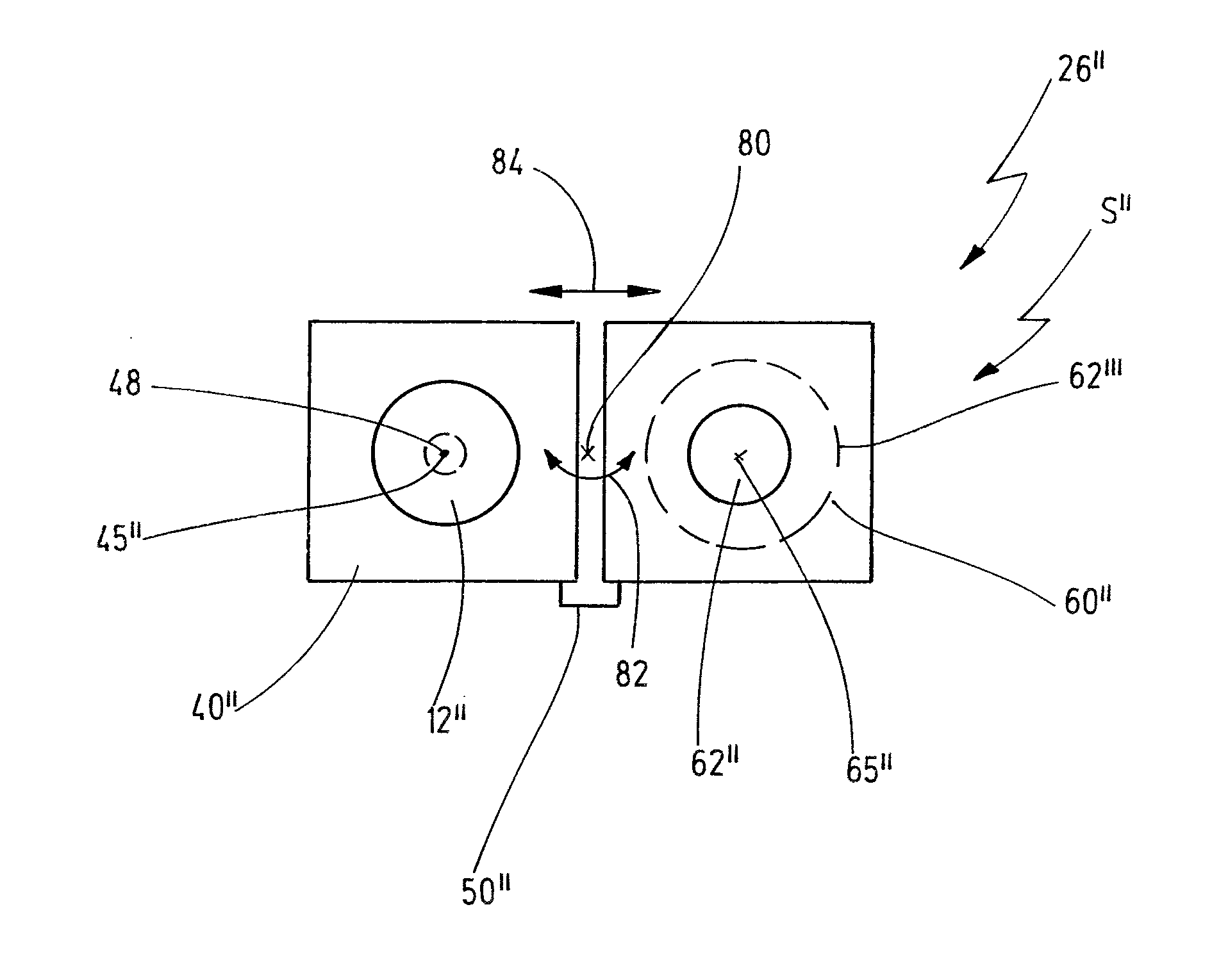
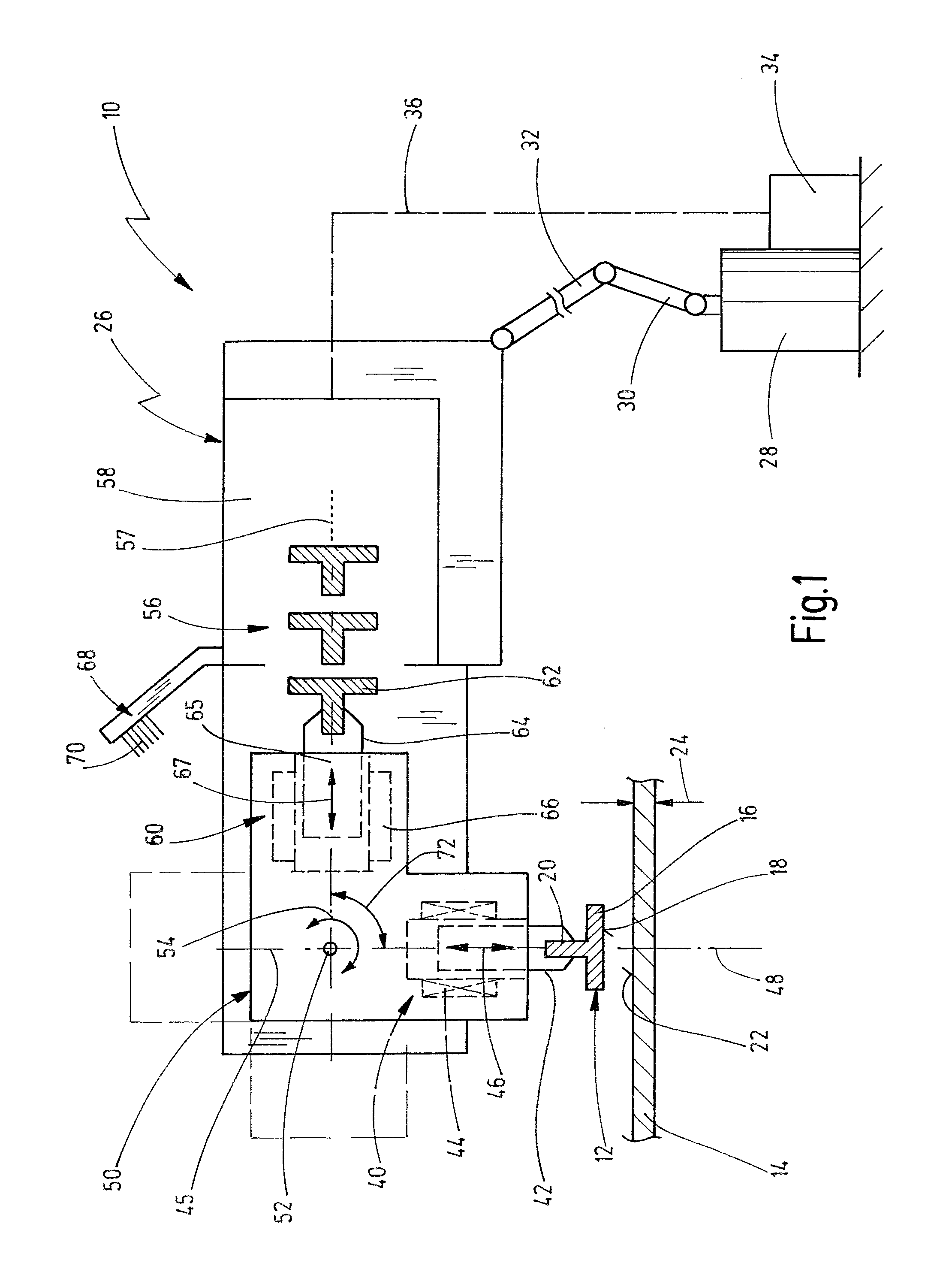
[0073]FIG. 1 shows a schematic representation of an embodiment of a joining apparatus according to the invention in the form of a stud welding apparatus which is designated in general by 10.

[0074]The welding apparatus 10 serves for the purpose of welding fastening elements 12 such as, for example, studs, on workpieces 14 such as, for example, metal sheets. The fastening elements 12 and / or the workpieces 14 can be produced from a metal material, for example steel, in particular, however, from a light metal such as aluminium. The fastening elements 12 have in each case a flange 16, on the underside of which a welding surface 18 is realized. On the upper side of the flange 16, the fastening elements 12 have a shank 20 which is preferably realized integrally with the flange 16. The workpiece 14 can be produced, in particular, from a sheet metal material which has a thickness 24 of less than or equal to 2 mm, in particular of less than or equal to 0.9 mm. The workpiece 14 has on an upper...


PUM

PropertyMeasurementUnit
angleaaaaaaaaaa
angleaaaaaaaaaa
angleaaaaaaaaaa

Abstract

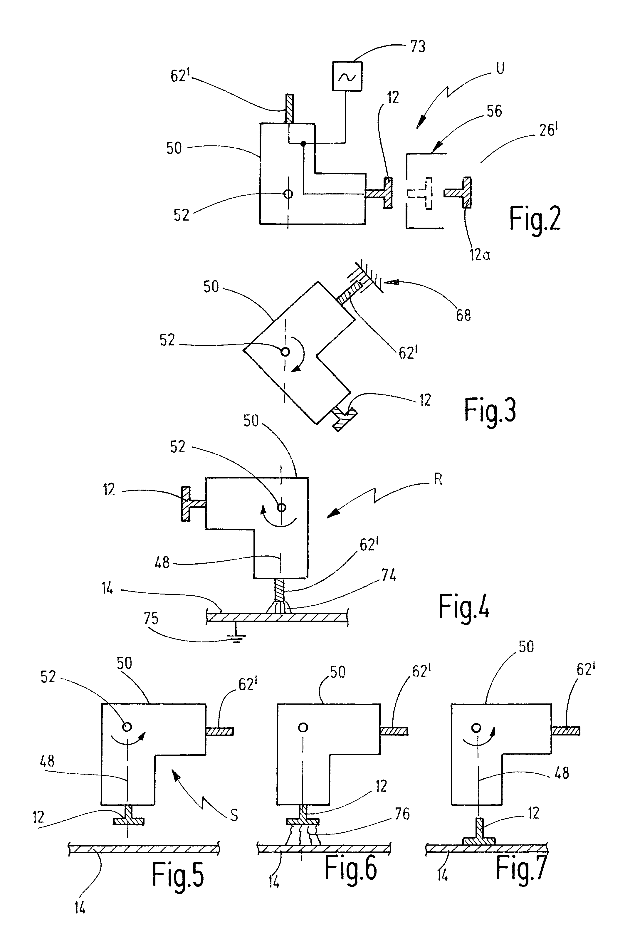
A welding apparatus for joining a weldable fastening element onto a workpiece by a welding process, wherein the welding apparatus comprises: an electric welding power source; a fastening element holding device for holding the fastening element during welding; a first drive device for moving the fastening element holding device along a first axis; a cleaning electrode holding device for holding a cleaning electrode along a second axis; and wherein the cleaning electrode is connectable to the electric welding power source. The fastening element holding device and the cleaning electrode holding device are mounted on a common tool carrier and the tool carrier is movable on a joining head by a tool carrier drive from a joining position to a cleaning position, and in the joining position the first axis defines a joining axis, and in the cleaning position the second axis is aligned with the joining axis.

Description

CROSS-REFERENCE TO RELATED APPLICATION[0001]This application claims priority from German Patent Application No. DE 102012015121.7, filed on Aug. 1, 2012, the disclosure of which is incorporated herein by reference.BACKGROUND OF THE INVENTION[0002]The present invention relates to a method for joining fastening elements such as studs on workpieces such as metal sheets, said method having the steps of preparing a joining surface of a fastening element and / or a joining surface of a workpiece and of bringing the fastening element and the workpiece together in such a manner that the fastening element is joined onto the workpiece, wherein, prior to the joining step, a cleaning step is carried out in order to clean the joining surface of the workpiece.[0003]In addition, the present invention relates to an apparatus for joining fastening elements on workpieces, in particular for carrying out the abovementioned method, said apparatus having a fastening element holding device for holding a fas...

Claims


Application Information

Patent Timeline
Patent Type & Authority Applications(United States)
IPC IPC(8): B23K11/02B23K11/36
CPCB23K11/36B23K11/02B08B7/0071B23K9/20B23K9/201B23K9/235
Inventor EISSARA, BAHSCHMITT, KLAUS-GISBERT
Owner NEWFREY
Learn More