Hybrid Closed Loop Speed Control using Open Look Position for Electrical Machines Controls

a technology of open look position and control of electrical machines, applied in the direction of motor/generator/converter stopper, dynamo-electric converter control, instruments, etc., can solve the problem that it is difficult for the electric drive system to accurately determine the absolute rotor speed or position and produce sufficient torque, and not all machines can use such high resolution

Active Publication Date: 2014-02-06
CATERPILLAR INC
View PDF21 Cites 5 Cited by
  • Summary
  • Abstract
  • Description
  • Claims
  • Application Information

AI Technical Summary

Problems solved by technology

Based on the desired use or application, however, not all machines may be able to use such high resolution speed wheels, but rather, may be required to use a low resolution speed wheel with much fewer teeth provided thereabout.
Use of such low resolution speed wheels makes it difficult for the electric drive system to accurately determine the absolute rotor speed or position and produce sufficient torque, especially while operating at zero or low speeds, such as during engine start routines.
However, due to the low resolution of the speed wheels being used and limitations associated with the sensors, the initial rotor position calculations may be inaccurate.
As the integrity of the tracking and overall control of the machine relies on the accuracy of the initial rotor position, any offsets caused by an inaccurate initial rotor position reading may be left uncorrected, which can further cause poor machine performance or prevent operation of the machine altogether.

Method used


Image

  • Hybrid Closed Loop Speed Control using Open Look Position for Electrical Machines Controls
  • Hybrid Closed Loop Speed Control using Open Look Position for Electrical Machines Controls
  • Hybrid Closed Loop Speed Control using Open Look Position for Electrical Machines Controls

Examples


Embodiment Construction

[0013]Reference will now be made in detail to specific embodiments or features, examples of which are illustrated in the accompanying drawings. Generally, corresponding reference numbers will be used throughout the drawings to refer to the same or corresponding parts.

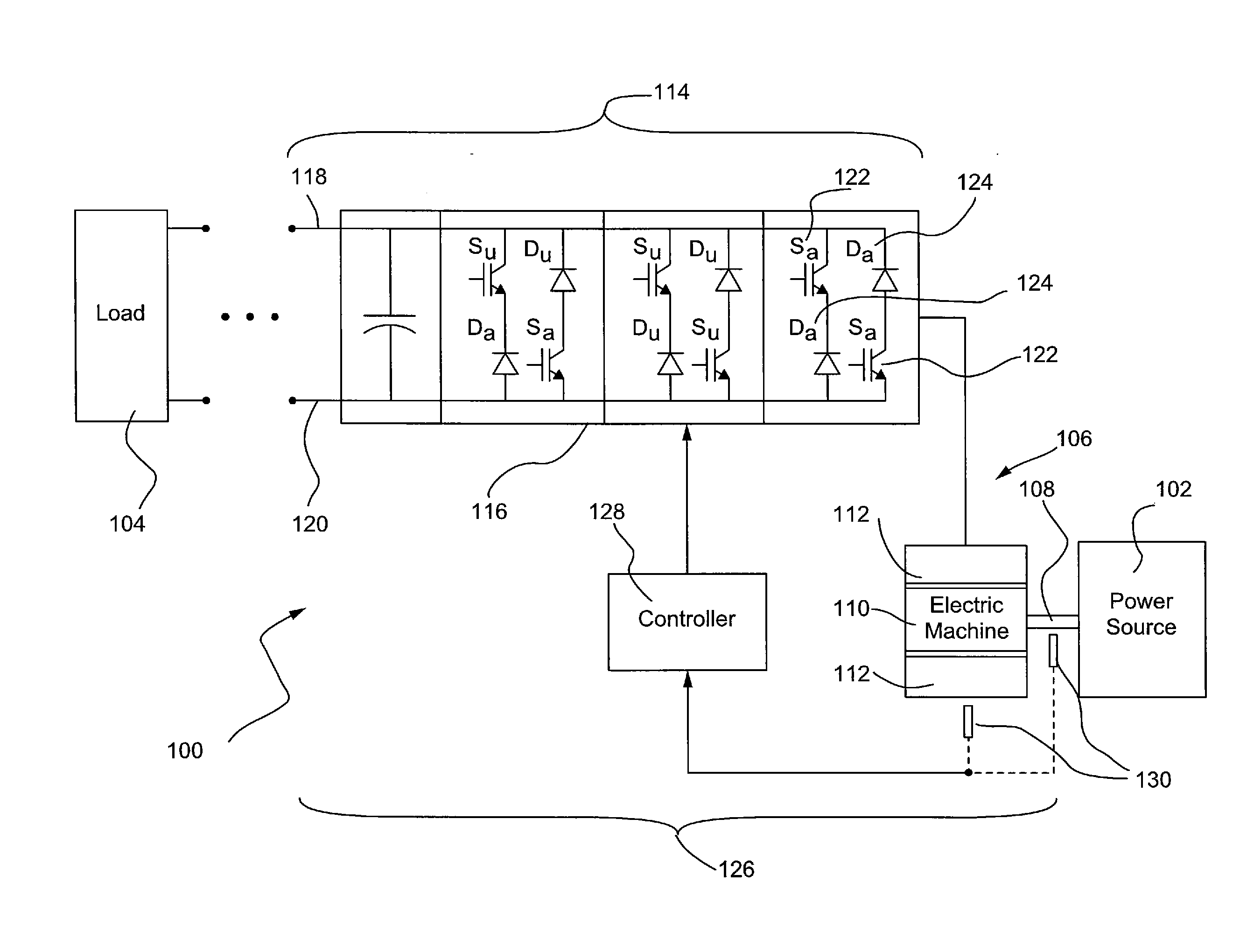
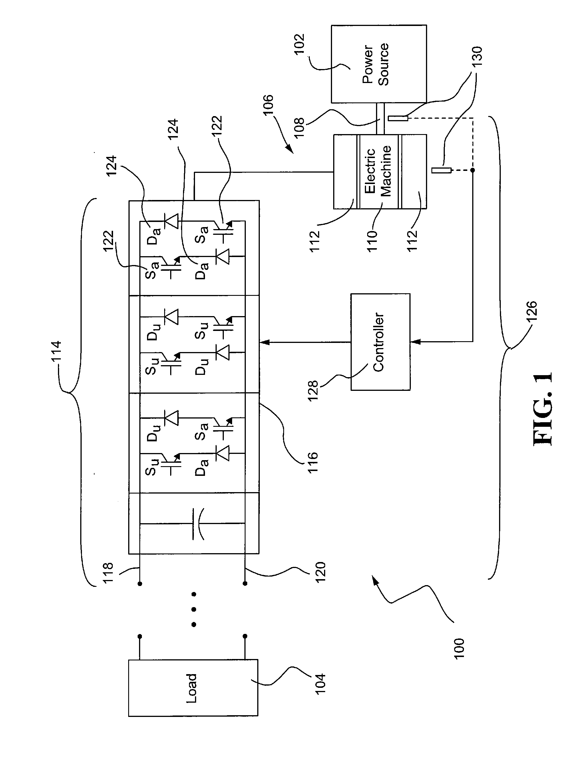
[0014]FIG. 1 schematically illustrates an exemplary electric drive 100 that may be employed to communicate power between a power source 102 and one or more electrical loads 104. The power source 102 may include, for example, a diesel engine, a gasoline engine, a natural gas engine, or any other source of energy commonly used with mobile machines. The power source 102 may also be used in conjunction with stationary applications and include, for instance, windmills, hydro-electric dams, batteries, fuel cells, or any other suitable source of energy. The load 104 may include one or more devices or components which receive electrical power. For example, with respect to industrial work machines or mobile work vehicles, the lo...


PUM


Abstract

A method of controlling speed of an electric machine having a rotor and a stator is provided. The method may comprise the steps of monitoring a desired speed and a measured speed of the rotor, generating a torque command based on the desired speed and the measured speed, and controlling phase current to the stator based on a hybrid closed loop analysis of the torque command, the measured speed and an estimated position of the rotor. The estimated rotor position may be derived at least partially from the desired speed.

Description

TECHNICAL FIELD[0001]The present disclosure relates generally to electric machines, and more particularly, to systems and methods for controlling the speed of electric machines.BACKGROUND[0002]An electric machine such as an electrical power generation system, genset, or the like, is generally used to convert one form of energy into another and may operate in a motoring mode to convert electrical power into mechanical or rotational power, or operate in a generating mode to convert mechanical or rotational power into electrical power. Among the various types of machines available for use with an electric drive assembly, switched reluctance (SR) machines have received great interest for being robust and cost-effective. While currently existing systems and methods for controlling such electric machines provide adequate control, there is still room for improvement.[0003]In order to efficiently operate the electric drive of a machine, it is important to accurately monitor the speed and / or...

Claims


Application Information

Patent Timeline
Patent Type & Authority Applications(United States)
IPC IPC(8): H02P29/00
CPCH02P23/03H02P25/0805
Inventor WAI, JACKSONGERDES, JESSETHORNE, JAMES MICHAEL
Owner CATERPILLAR INC
Why Eureka
Try Eureka