Antenna device and communication terminal apparatus

a technology of communication terminal and antenna device, which is applied in the direction of antenna details, polarised antenna unit combinations, antennas, etc., can solve the problems of limited direction in which the coil antenna has sufficient sensitivity, and difficulty in having a sufficient communication distance in the direction,

Inactive Publication Date: 2014-02-06
MURATA MFG CO LTD
View PDF14 Cites 178 Cited by
  • Summary
  • Abstract
  • Description
  • Claims
  • Application Information

AI Technical Summary

Benefits of technology

[0033]According to various preferred embodiments of the present invention, the magnetic flux density in a direction different from the winding axes of the first and second coil antennas of the antenna device is significantly improved.

Problems solved by technology

As a result, although a sufficient communication distance can be ensured in the direction of the winding axis, the communication distance in the direction at 45 to 90 degrees to the winding axis is not enough.
However, it is still difficult to have a sufficient communication distance in the direction inclined at 45 degrees or greater to the winding axis.
The direction in which the coil antenna has sufficient sensitivity is therefore limited to the direction vertical or parallel to the surface of the printed board.
Moreover, when metals such as wiring and ground are provided in a printed circuit board installed with a coil antenna, or when metal parts such as chip capacitors or IC chips are arranged around the installed coil antenna, these metals prevent formation of a magnetic flux and make it impossible to ensure a sufficient communication distance.
In conventional coil antennas, it is difficult to form a magnetic flux so as to avoid these metals because the magnetic flux density is the largest in the direction of the winding axis of the coil.

Method used


Image

  • Antenna device and communication terminal apparatus
  • Antenna device and communication terminal apparatus
  • Antenna device and communication terminal apparatus

Examples


first preferred embodiment

[0084]An antenna device according to a first preferred embodiment of the present invention preferably is configured as a built-in antenna for a mobile communication system and is used as a reader / writer-side antenna or a tag-side antenna for the HF band, for example, such as Felica (registered trademark) and NFC (Near Field Communication).

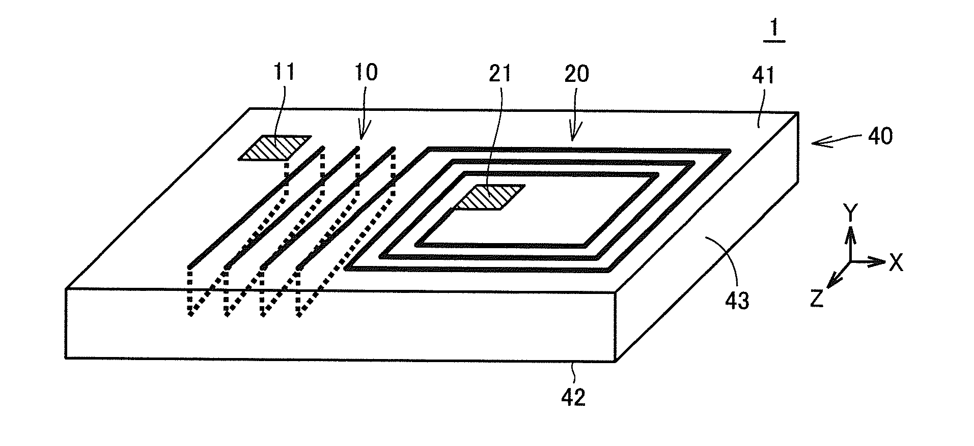
[0085]FIG. 1 is an external view schematically showing a configuration of an antenna device 1 in a first preferred embodiment of the present invention.

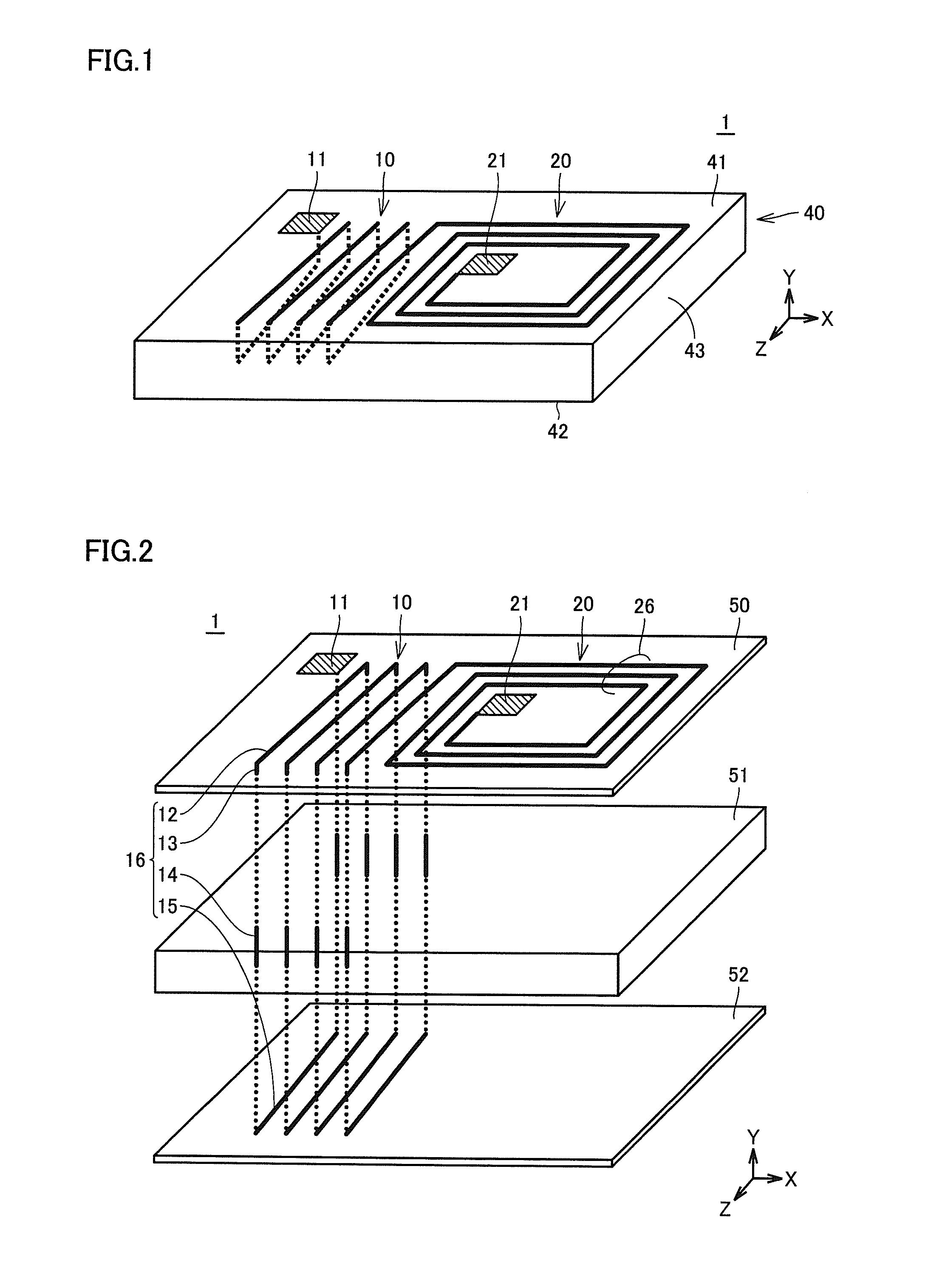
[0086]FIG. 2 is a diagram illustrating a structure of antenna device 1 in FIG. 1.

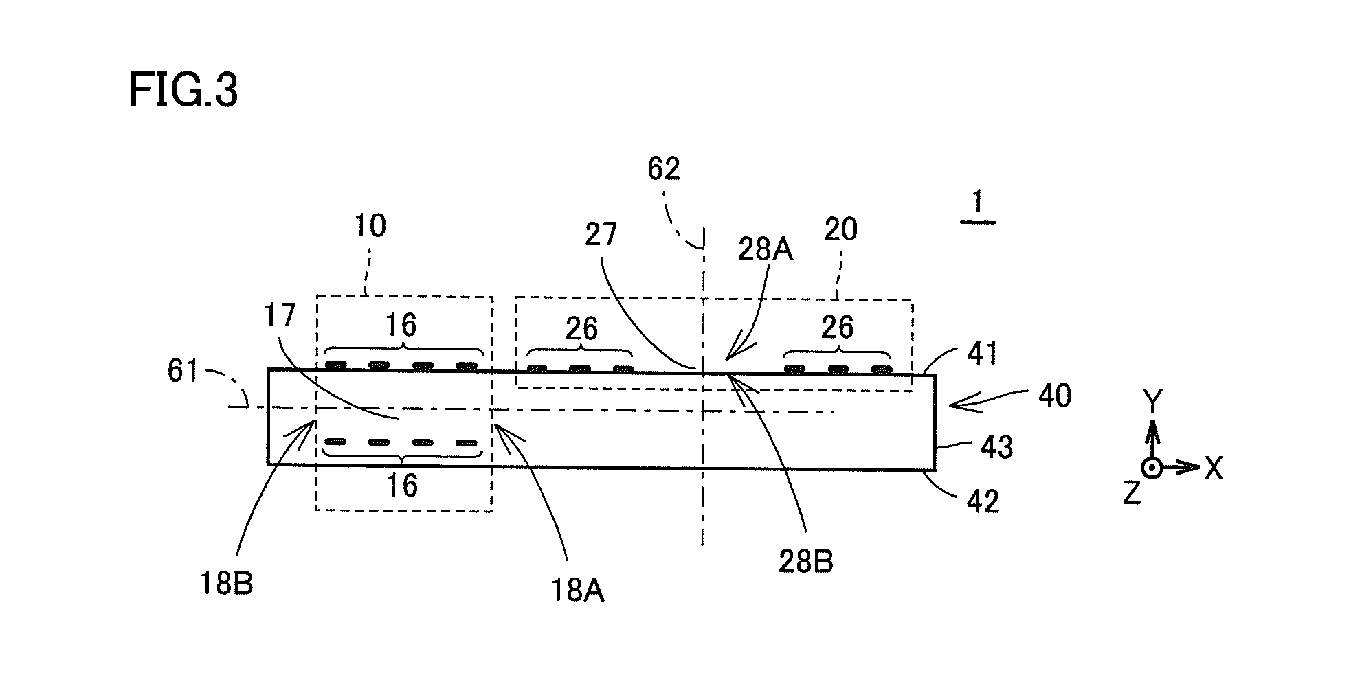
[0087]FIG. 3 is a cross-sectional view showing antenna device 1 in FIG. 1 as viewed from the Z direction parallel to a main surface 41.

[0088]Referring to FIG. 1 to FIG. 3, antenna device 1 includes a body 40 including a dielectric or an insulating magnetic material, or including both, a first coil antenna 10 including a winding axis extending approximately in the X direction, and a second coil antenna 20 including a wind...

second preferred embodiment

[0144]FIG. 16 is an external view schematically showing a configuration of an antenna device 5 in a second preferred embodiment of the present invention.

[0145]Antenna device 5 in the present preferred embodiment is provided by preferably adding a conductive layer 83 serving as a boost antenna to the antenna device in the first preferred embodiment, as shown in FIG. 16. Conductive layer 83 is arranged in proximity to first main surface 41 so as to extend along first main surface 41 of body 40. Conductive layer 83 has a hole portion 84 passing through conductive layer 83 in the vertical direction and a slit-shaped notch portion 85 reaching hole portion 84. Notch portion 85 brings hole portion 84 into communication with the outer peripheral space of conductive layer 83 and passes through conductive layer 83 in the vertical direction. When viewed two-dimensionally from the direction vertical to first main surface 41, hole portion 84 of conductive layer 83 is arranged to overlap the open...

third preferred embodiment

[0151]FIG. 18 is an external view schematically showing a configuration of an antenna device6 in a third preferred embodiment of the present invention.

[0152]FIG. 19 is a cross-sectional view showing antenna device 6 in FIG. 18 as viewed from the Z direction parallel to main surface 41.

[0153]Antenna device 6 in the present preferred embodiment is preferably provided by adding a third coil antenna 30 to antenna device 1 in the first preferred embodiment, as shown in FIG. 18 and FIG. 19. In the case in FIG. 18 and FIG. 19, coil conductors 16 and 36 of first and third coil antennas 10C and 30 are arranged to extend from the inside of body 40 to both of first and second main surfaces 41 and 42.

[0154]Referring to FIG. 18 and FIG. 19, first coil antenna 10C, second coil antenna 20, and third coil antenna 30 are connected in series in this order between first feed terminal 11 and second feed terminal 31. In the case in FIG. 18, feed terminals 11 and 31 are located on first main surface 41 o...


PUM


Abstract

An antenna device includes a body and first and second coil antennas. Each coil conductor of the first and second coil antennas is provided at least one of inside and on a surface of the body. The first coil antenna includes a winding axis intersecting at least one side surface of the body. The second coil antenna includes a winding axis intersecting first and second main surfaces of the body.

Description

BACKGROUND OF THE INVENTION[0001]1. Field of the Invention[0002]The present invention relates to an antenna device and, relates to an antenna device for use as a built-in antenna for mobile communication terminals, for example.[0003]2. Description of the Related Art[0004]As a system for identifying and managing goods, an RFID system is known which communicates between a reader / writer and an RFID (Radio Frequency Identification) tag in a non-contact manner and transmits information between the reader / writer and the RFID tag. In this RFID system, predetermined information is transmitted / received as a high-frequency signal between the antenna of the RFID tag and the antenna of the reader / writer.[0005]Coil antennas formed by winding a conductor wire into a coil shape are common among antennas for use in HF-band (13.56 MHz band) RFID systems. As such a coil antenna, a planar coil antenna formed by winding a conductor pattern in a planar manner on a substrate surface is generally used, fo...

Claims


Application Information

Patent Timeline
Patent Type & Authority Applications(United States)
IPC IPC(8): H01Q21/24
CPCH01Q21/24H01Q1/243H01Q1/38H01Q7/00H01Q7/06
Inventor KATO, NOBORUOZAWA, MASAHIRO
Owner MURATA MFG CO LTD
Why Eureka
Try Eureka