Directionally illuminated waveguide arrangement

a waveguide and waveguide technology, applied in the direction of instrumentation, lighting and heating apparatus, planar/plate-like light guides, etc., can solve the problems of increased image crosstalk, non-uniform viewing windows, and limited display viewing freedom, so as to improve the functionality and reduce the range of angles , the effect of large area display

Active Publication Date: 2014-02-06
REALD SPARK LLC
View PDF8 Cites 111 Cited by
  • Summary
  • Abstract
  • Description
  • Claims
  • Application Information

AI Technical Summary

Benefits of technology

[0012]The present embodiments achieve a two dimensional array of windows from a display apparatus comprising an imaging directional backlight, and in particular stepped waveguide imaging directional backlights comprising further input focusing optics. Such a two dimensional window array advantageously may achieve enhanced functionality including vertical look-around, head tilt tracking, landscape-portrait operation and an increased number of independently tracked observers and is thus particularly suitable for large area display. Further, the present embodiments may efficiently limit the range of angles propagating within the stepped waveguide that may be used to achieve more compact display structures.
[0013]Embodiments herein may provide an autostereoscopic display with large area and thin structure. Further, as will be described, the optical valves of the present disclosure may achieve thin optical components with large back working distances. Such components can be used in directional backlights, to provide directional displays including autostereoscopic displays. Further, embodiments may provide a controlled illuminator for the purposes of an efficient autostereoscopic display.

Problems solved by technology

Gaps between the pixels, for example for electrodes, typically produce non-uniform viewing windows.
Undesirably such displays exhibit image flicker as an observer moves laterally with respect to the display and so limit the viewing freedom of the display.
Such flicker can be reduced by defocusing the optical elements; however such defocusing results in increased levels of image cross talk and increases visual strain for an observer.

Method used


Image

  • Directionally illuminated waveguide arrangement
  • Directionally illuminated waveguide arrangement
  • Directionally illuminated waveguide arrangement

Examples


Embodiment Construction

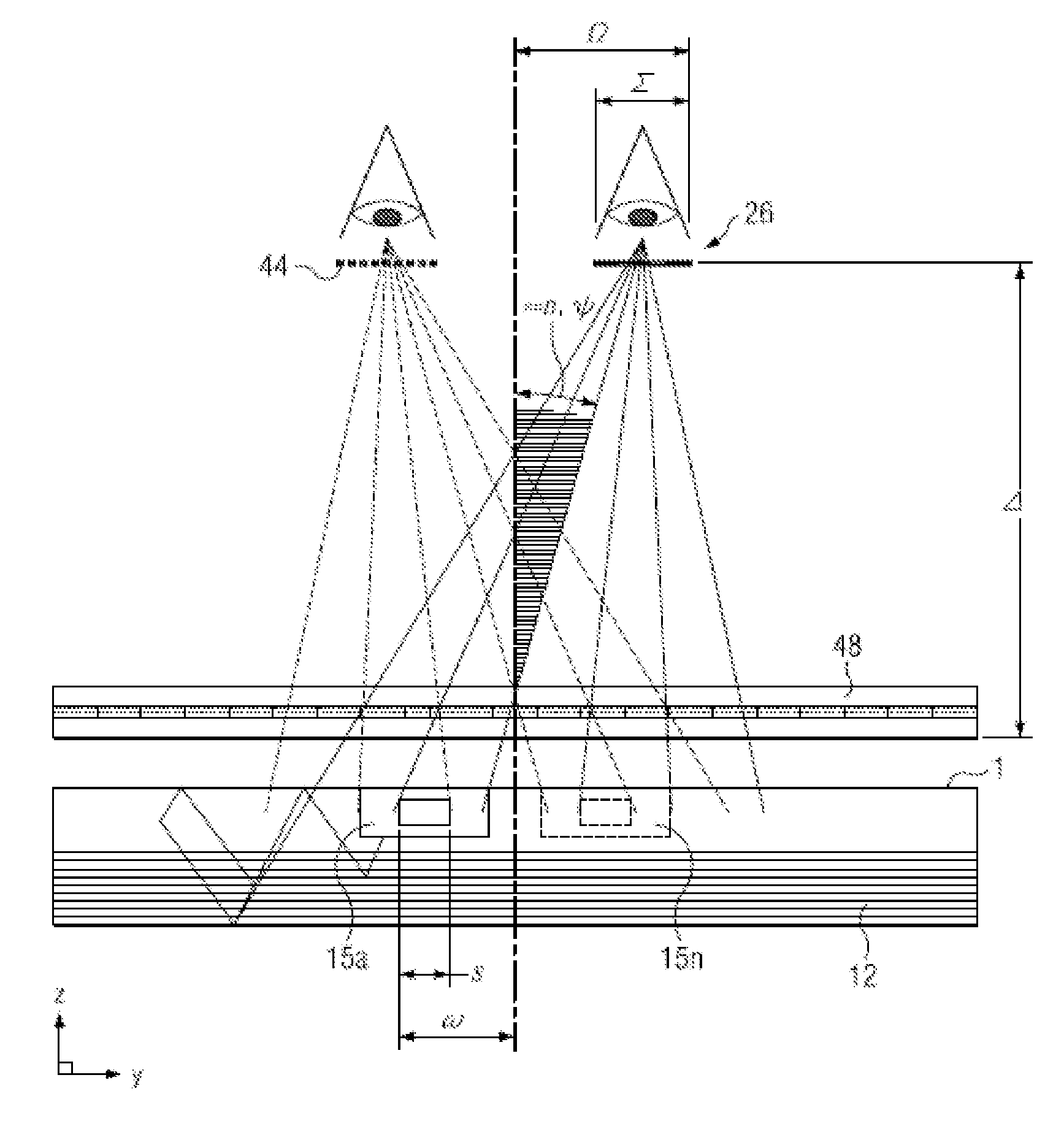
[0097]Time multiplexed autostereoscopic displays can advantageously improve the spatial resolution of autostereoscopic display by directing light from all of the pixels of a spatial light modulator to a first viewing window in a first time slot, and all of the pixels to a second viewing window in a second time slot. Thus an observer with eyes arranged to receive light in first and second viewing windows will see a full resolution image across the whole of the display over multiple time slots. Time multiplexed displays can advantageously achieve directional illumination by directing an illumination array through a substantially transparent time multiplexed spatial light modulator using directional optical elements, wherein the directional optical elements substantially form an image of the illumination array in the window plane.

[0098]The uniformity of the viewing windows may be advantageously independent of the arrangement of pixels in the spatial light modulator. Advantageously, suc...


PUM

PropertyMeasurementUnit
sizeaaaaaaaaaa
sizeaaaaaaaaaa
back working distanceaaaaaaaaaa

Abstract

Disclosed is a light guiding valve apparatus comprising an optical valve, a two dimensional light source array and a focusing optic for providing large area collimated illumination from localized light sources. A stepped waveguide may be a stepped structure, in which the steps may be extraction features optically hidden to guided light, propagating in a first forward direction. Returning light propagating in a second backward direction may be refracted, diffracted, or reflected by the features to provide discrete illumination beams exiting from the top surface of the waveguide. A two dimensional array of viewing windows may be produced. Such controlled illumination may provide for efficient, multi-user autostereoscopic displays with wide viewing freedom and low cross talk and near-eye displays that are substantially transparent.

Description

CROSS-REFERENCE TO RELATED APPLICATIONS[0001]This application claims priority to U.S. Patent App. No. 61 / 648,873, entitled “Imaging directional backlight with two dimensional window arrays”, filed 18 May 2012 (ReaID Ref: 315000), and to U.S. Patent App. No. 61 / 649,141, entitled “Planar display apparatus”, filed 18 May 2012 (ReaID Ref: 329000), the entireties of which are herein incorporated by reference.TECHNICAL FIELD[0002]This disclosure generally relates to illumination of light modulation devices, and more specifically relates to light guides for providing large area illumination from localized light sources for use in 2D, 3D, and / or autostereoscopic display devices.BACKGROUND[0003]Spatially multiplexed autostereoscopic displays typically align a parallax component such as a lenticular screen or parallax barrier with an array of images arranged as at least first and second sets of pixels on a spatial light modulator, for example an LCD. The parallax component directs light from ...

Claims


Application Information

Patent Timeline
Patent Type & Authority Applications(United States)
IPC IPC(8): G02F1/01F21V8/00G02B27/22G02B27/01G02B6/26G02B6/32G02B30/33
CPCG02F1/011G02B6/262G02B6/0013G02B27/225G02B27/0172G02B6/32H04N13/32H04N13/368H04N13/371H04N13/376H04N13/383H04N13/344H04N13/378H04N13/356H04N13/363H04N13/38G02B6/0048H04N13/337H04N2013/403H04N13/354H04N13/324H04N2013/405G02B6/0055G02B30/33G02B6/10G02B6/102G02B27/02H04N13/00G02B6/0023G02B6/0061G02B6/0068G02B2027/0134G02B2027/0178G02C7/02
Inventor WOODGATE, GRAHAM J.ROBINSON, MICHAEL G.HARROLD, JONATHANSCHUCK, MILLER H.
Owner REALD SPARK LLC
Why Eureka
Try Eureka