System, method and apparatus for electromagnetic detection and analysis of biometric information

a biometric information and electromagnetic detection technology, applied in the field of systems, methods and apparatus for sensing and analyzing biometric information, can solve the problems of relatively large sensors, inability to carry out mobile or portable devices, and inability to circumvent systems,

Active Publication Date: 2014-02-06
MCNULTY SCOTT
View PDF0 Cites 18 Cited by
  • Summary
  • Abstract
  • Description
  • Claims
  • Application Information

AI Technical Summary

Benefits of technology

[0015]It is a further objective of the invention to provide an electrical current at a level below that necessary to cause physiological reaction with an individual's dermal surface. For example, the electrical current may be an alternating current between about 0.01 milliamps and about 25 milliamps and having a frequency of about 60 Hz or less, and more specifically between about 0.5 milliamps and about 5.0 milliamps and having a frequency of between about 20 Hz and 50 Hz. Alternatively, insulating materials may be used in connection with the electrically charged conductive surface to protective against unwanted physiological reaction with the individual's dermal surface. It will be understood that in such instances, a higher electrical current having an increased frequency (e.g., 64 MHz or higher) may be used with the present invention to induce an electromagnetic field sufficient to provide measurable variations, fluctuations or disturbances to the electromagnetic field corresponding to the physical contours of the sweat gland pores on an individual's dermal surface.

Problems solved by technology

However, these basic traits also make the biometric identification systems vulnerable to spoofing.
Most of these systems involve relatively large sensors which are unacceptable for mobile or portable devices.
These systems, however, can be circumvented because they operate by comparing the detected liveness measure value to a predetermined acceptable range.

Method used


Image

  • System, method and apparatus for electromagnetic detection and analysis of biometric information
  • System, method and apparatus for electromagnetic detection and analysis of biometric information
  • System, method and apparatus for electromagnetic detection and analysis of biometric information

Examples


Embodiment Construction

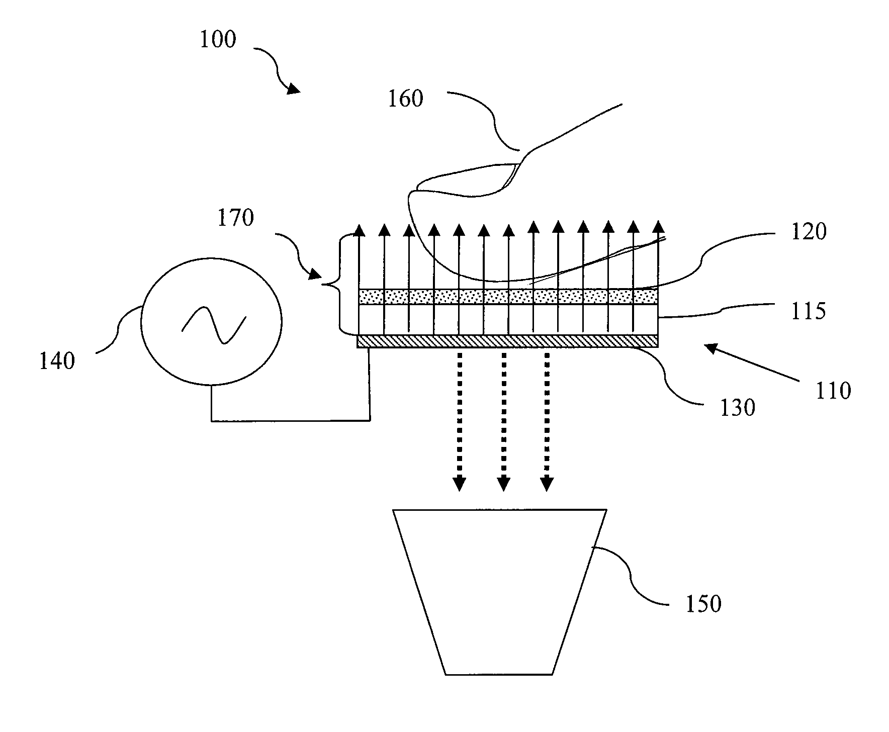
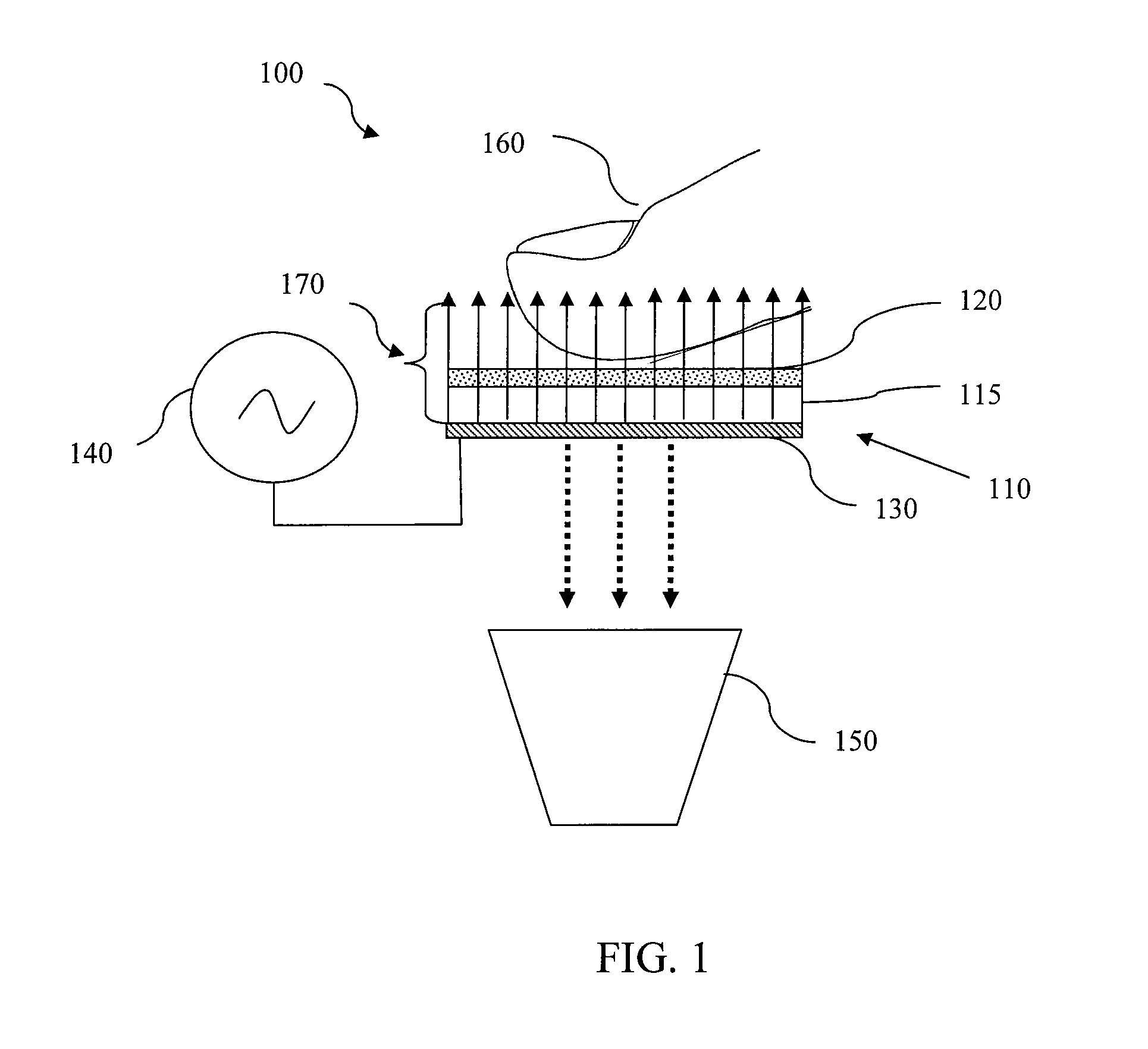
[0036]FIG. 1 is a schematic diagram illustrating an embodiment of the present invention for biometric identification and proof of liveness based on the detection and analysis of sweat gland pores on an individual's fingerpad. As shown in FIG. 1, the biometric identification apparatus 100 comprises a voltage source 140, a transparent electrode 110, and an image capture device 150. Voltage source 140 is configured to generate an electrical current through transparent electrode 110, which induces an electromagnetic field 170. Preferably, voltage source 140 is an alternating current voltage source and the resulting alternating electrical current transmitted through transparent electrode 110 is sufficient to induce an electromagnetic field of the necessary magnitude to stimulate and excite the molecules associated with an individual's dermal surface and cause compounds within the molecules to fluoresce. In one embodiment, the resulting alternating electrical current may be between about ...


PUM


Abstract

An apparatus, method and system are provided for sensing at least one biometric measure of an individual. An electrical current flows through an electrode to induce an electromagnetic field. The electromagnetic field stimulates and excites the molecules associated with the sweat gland pores and causes molecular compounds to fluoresce. An image of the fluoresced dermal surface is obtained and a biometric function is performed with data derived from the image. Alternatively, sweat gland pore biometric information may be derived from variations, fluctuations or disturbances to the electromagnetic field induced by the electrical current.

Description

FIELD OF THE INVENTION[0001]The present invention relates to a system, method and apparatus for sensing and analyzing biometric information. More specifically, the present invention relates to a system, method and apparatus for inducing an electromagnetic field and detecting sweat gland pores as an identification, authentication and / or liveness biometric measure.BACKGROUND[0002]Biometric identification systems use sensor technologies to obtain information regarding an individual's unique physical characteristics and compare the obtained information with verified reference information to confirm the identity of the individual. Known biometric identification systems have used optical, thermal, capacitive, impedance, radio-frequency, conductance and ultrasonic based sensors for detecting biometric information.[0003]Physical characteristics that are commonly used for biometric identification include unique features from an individual's face, iris, hand geometry, vein pattern, palm and f...

Claims


Application Information

Patent Timeline
Patent Type & Authority Applications(United States)
IPC IPC(8): G06K9/00
CPCG06K9/00013G06V40/1394G06V40/1318
Inventor MCNULTY, SCOTT
Owner MCNULTY SCOTT
Why Eureka
Try Eureka