

Stabilizing Platform
a platform and stabilizer technology, applied in the field of videography, photography and/or surveillance, can solve the problems of affecting the operation the movement of the payload device, and the inability to adjust the posture of the patient, so as to achieve the effect of rapid response to the adjustment of the postur
- Summary
- Abstract
- Description
- Claims
- Application Information
AI Technical Summary
Benefits of technology
Problems solved by technology
Method used
Image

Examples
exemplary embodiment 1
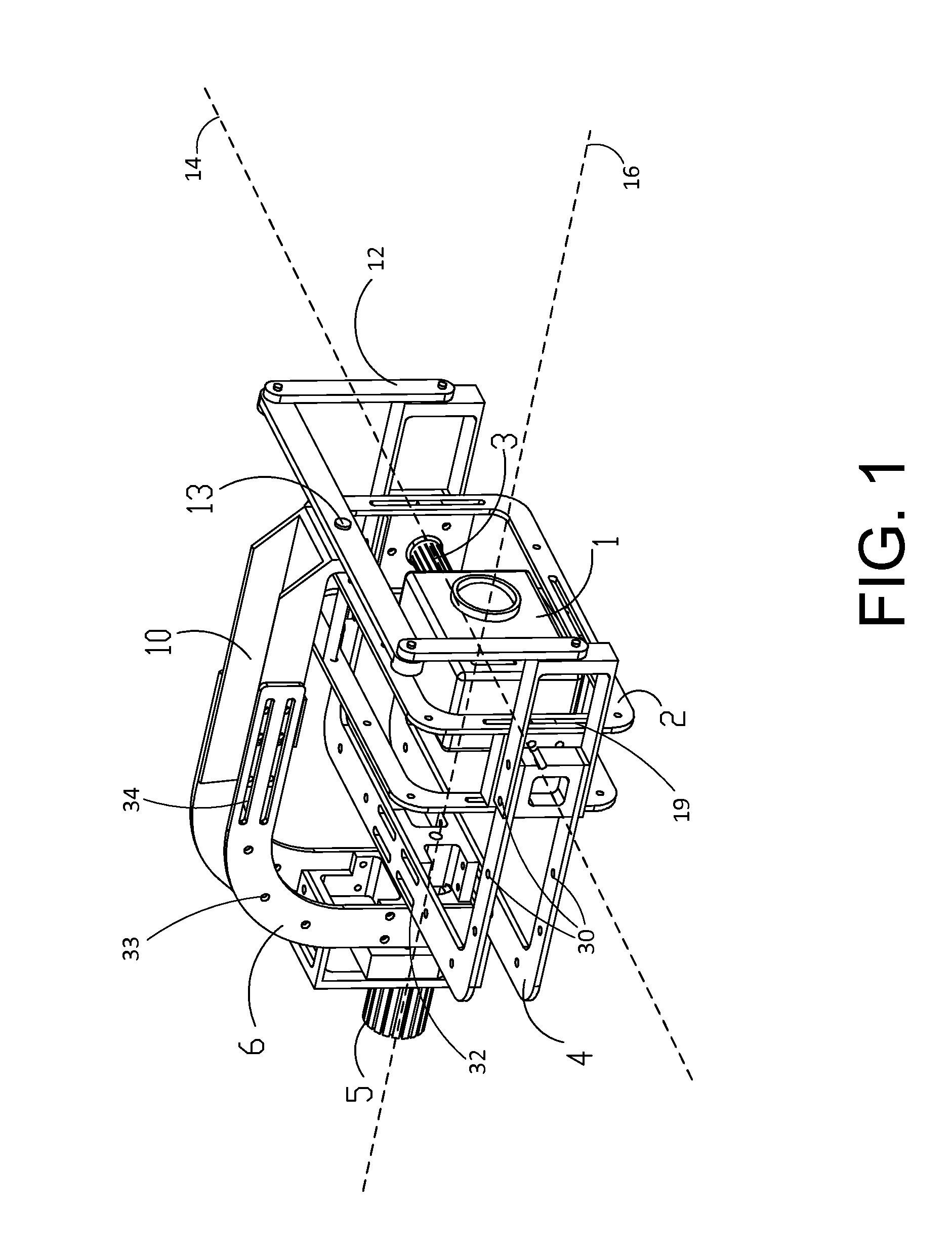
[0033]FIG. 1 illustrates a structural schematic view of stabilizing platform, in accordance with an embodiment of the present invention. The stabilizing platform may be configured to hold a payload device 1 such as an imaging device or a non-imaging device (e.g., microphone, particle detector, sample collector). An imaging device may be configured to acquire and / or transmit one or more images of objects within the imaging device's field of view. Examples of an imaging device may include a camera, a video camera, cell phone with a camera, or any device having the ability to capture optical signals. A non-imaging device may include any other devices such as for collecting or distributing sound, particles, liquid, or the like. Examples of non-imaging devices may include a microphone, a loud speaker, a particle or radiation detector, a fire hose, and the like.
[0034]In some embodiments, the stabilizing platform may be adapted to be mounted or otherwise coupled to a movable object such as...
exemplary embodiment 2
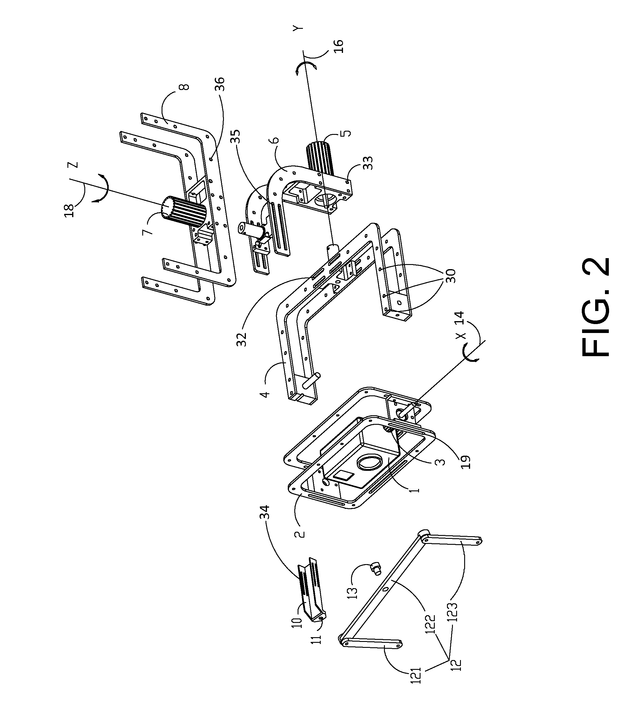
[0049]FIGS. 2-6 illustrate example views of a stabilizing platform, in accordance with a second embodiment of the present invention. The platform illustrated in this embodiment is similar to that illustrated in the first embodiment as discussed in connection with FIG. 1. In some embodiments, the stabilizing platform may be adapted to be mounted or otherwise coupled to a movable object such as a motorized or non-motorized vehicle or vessel, robot, human, animal, or the like. For example, the stabilizing platform may be mounted to the base of a manned or unmanned aerial vehicle (UAV).
[0050]However, as illustrated by FIGS. 2-6, the stabilizing platform in the second embodiment provides three axes of rotation for a payload device mounted therein, instead of the two axes of rotation provided by the stabilizing platform in the first embodiment. More specifically, as shown in FIG. 2, the payload device is allowed to rotate around the pitch (X) axis 14, roll (Y) axis 16, and yaw (Z) axis 18...
exemplary embodiment 3
[0062]A third embodiment of the present invention may be provided. The third embodiment may be similar to the first embodiment and the second embodiment, except that the fastener 13 is replaced with a fourth motor which directly drives the connecting assembly 12 to rotate relative to the third frame member 6. Thus, the connecting assembly 12 brings the second frame member 4 to rotate therewith. Hence, the fourth motor may be auxiliary to the second motor 5. It may be appreciated that, in some embodiments, the fourth motor may replace the second motor 5 and serve as a motive power source by which the second frame member 4 rotates relative to the third frame member 6. In such embodiments, the second motor 5 may be optional and the motor assembly may only include the first motor 3, the third motor 7 and the fourth motor.
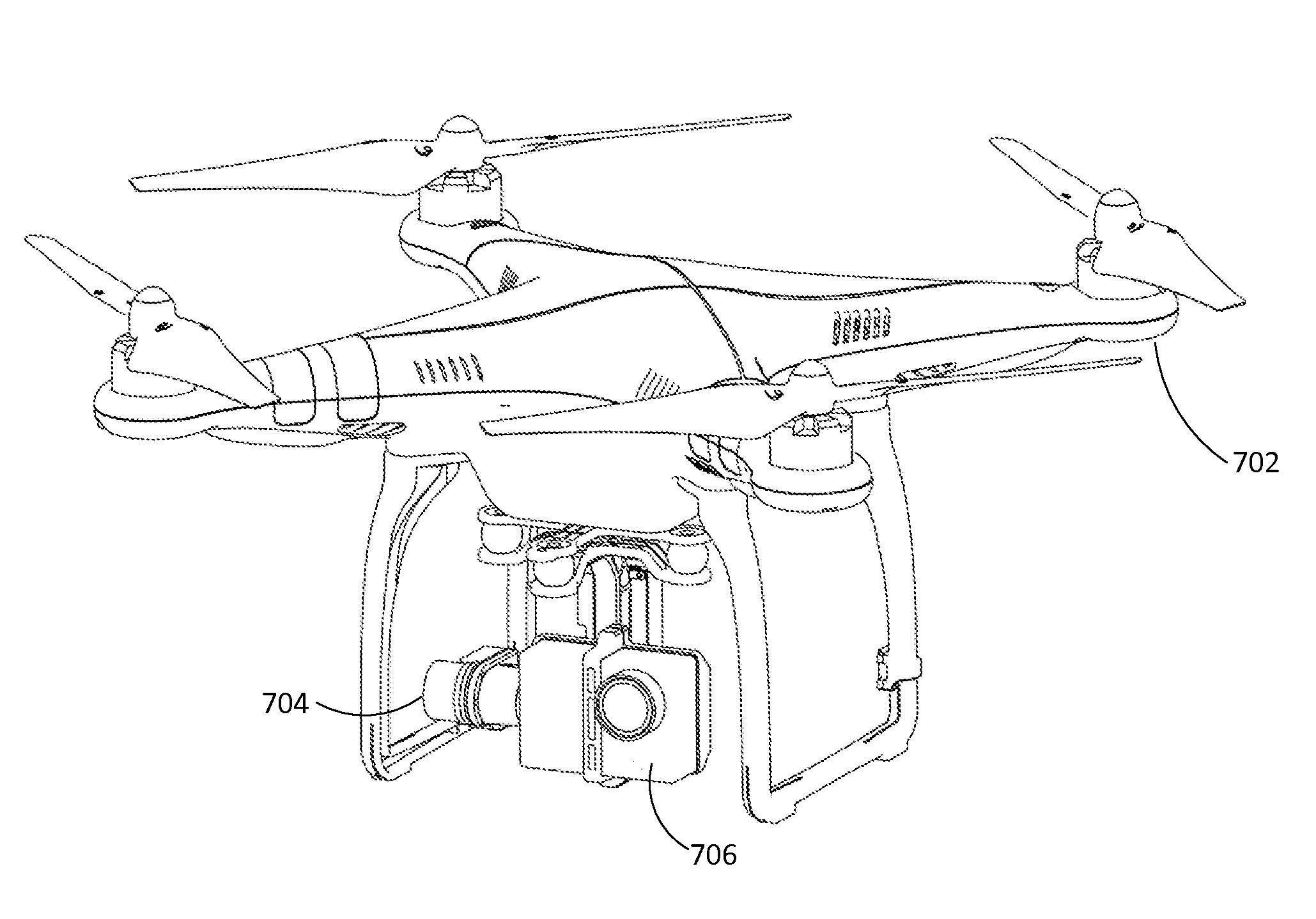
[0063]In various embodiments, the stabilizing platform discussed herein may be mounted or otherwise coupled to a movable object such as those described herein. FIG. 7 i...
PUM
 Abstract
Description
Claims
Application Information