Microfluidic PCR device

a microfluidic and pcr technology, applied in the field of disposable microfluidic devices, can solve the problems of insufficient parallelism of microfluidic platforms, overall cost, and cost of both disposable devices and reagents, and achieve the effects of reducing or eliminating cross contamination among wells, high degree of parallelism, and small sample volum

Active Publication Date: 2014-02-06
STMICROELECTRONICS SRL +1
View PDF2 Cites 23 Cited by
  • Summary
  • Abstract
  • Description
  • Claims
  • Application Information

AI Technical Summary

Benefits of technology

[0014]The aim of the present disclosure is to provide a disposable microfluidic device that overcomes the aforementioned limitations, in particular a microfluidic device wherein cross contamination among wells is reduced or eliminated during use, while providing a high degree of parallelism, and taking advantage of small sample volumes, and speed in obtaining results.

Problems solved by technology

However, known microfluidic platforms do not provide sufficient parallelism (i.e. number of reaction chambers working in parallel), combined with small volumes of reagents and sample (e.g., less than 300 nl per chamber), high versatility, ease of use and cost effectiveness, all necessary in order to improve the manufacturing scalability in large volumes of the fabricated disposable devices and also to reduce the overall cost of the envisaged solution, including the cost of both the disposable device and reagents.
Moreover, known microfluidic devices having a plurality of reaction chambers or wells formed in a same substrate, still suffer from cross contamination between the wells (fluid / reagent within one well mix with the fluid / reagent from another well).
This drawback is identifiable in known microfluidic devices irrespectively of the particular use of such microfluidic devices.

Method used


Image

  • Microfluidic PCR device
  • Microfluidic PCR device
  • Microfluidic PCR device

Examples


Embodiment Construction

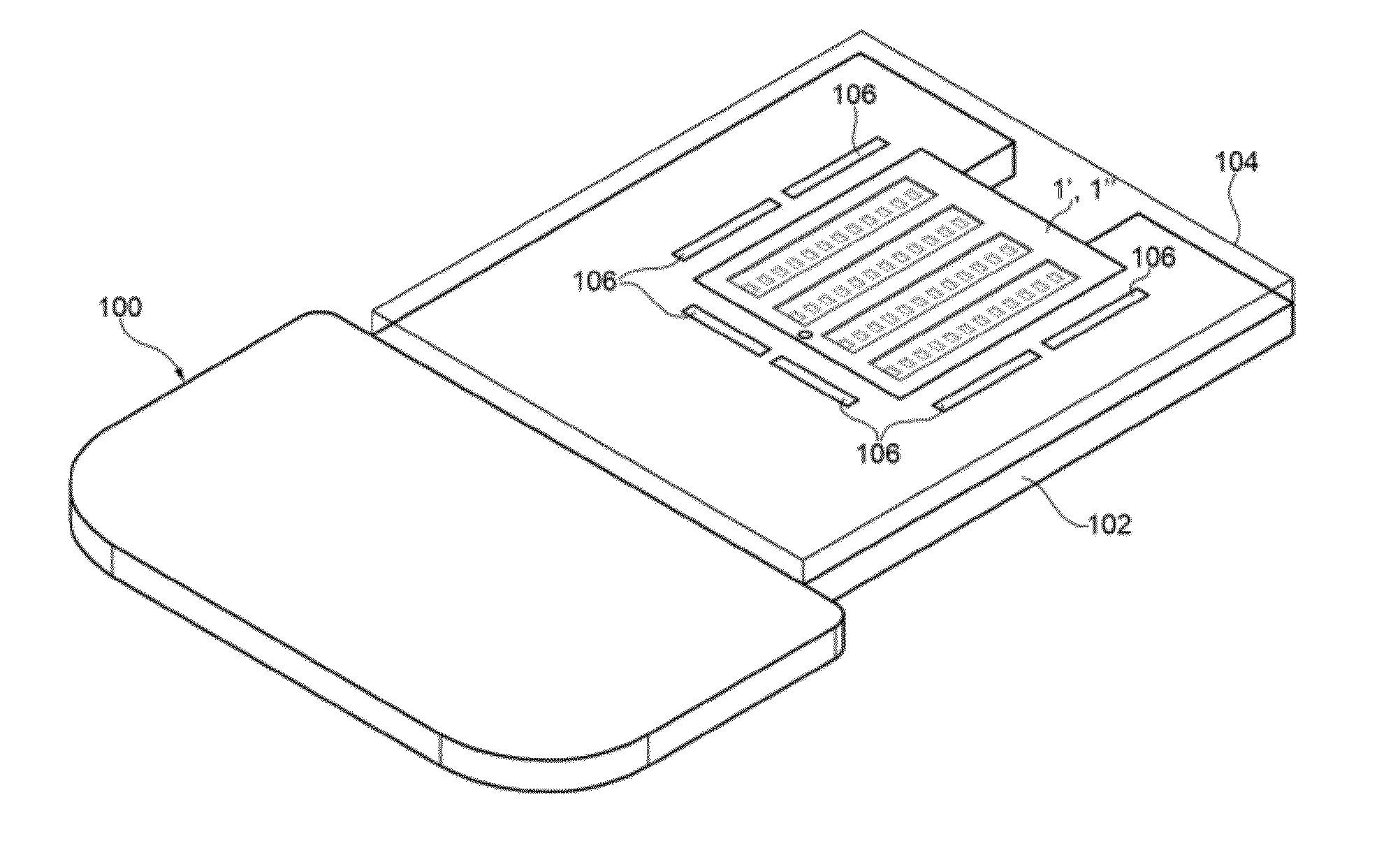
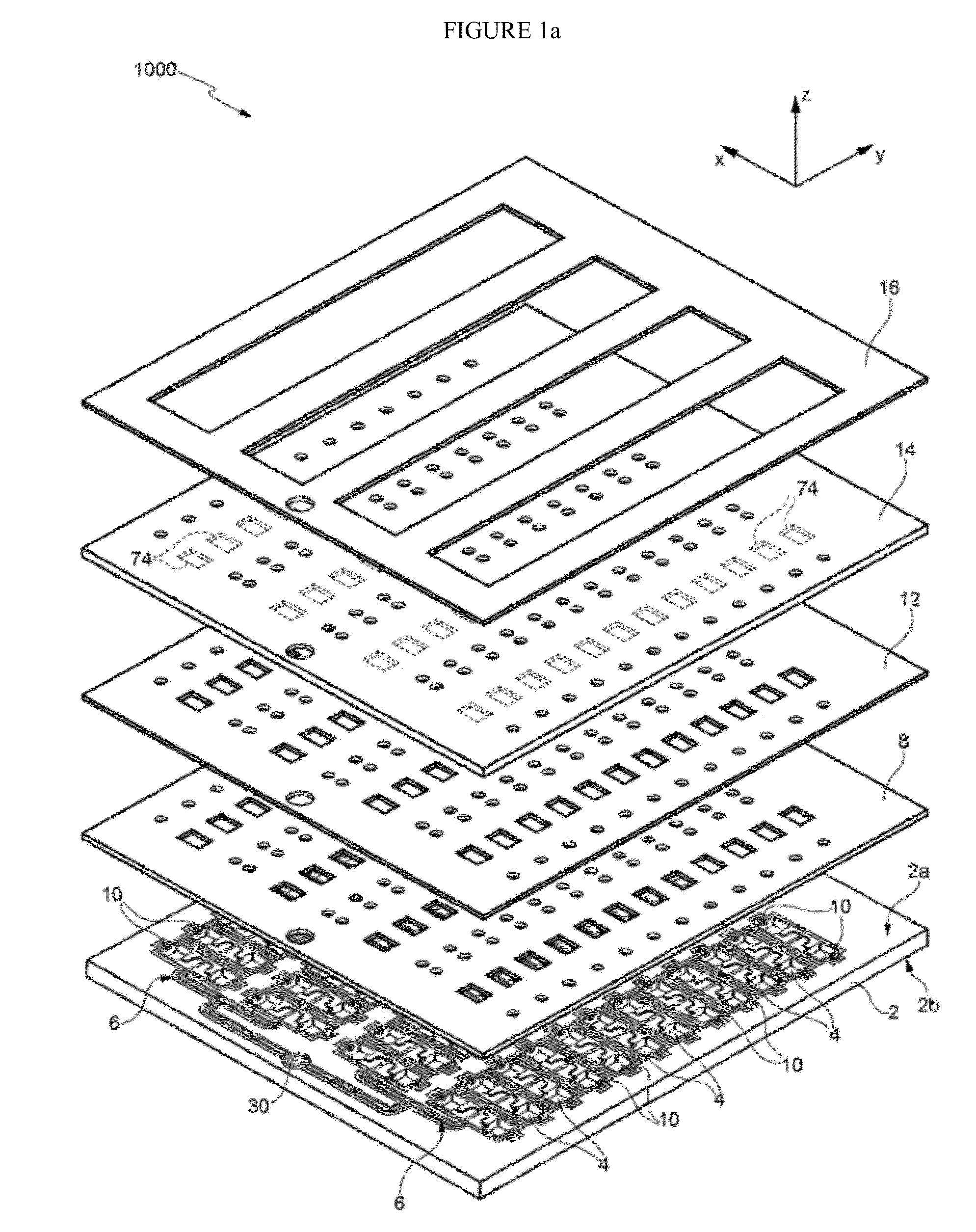
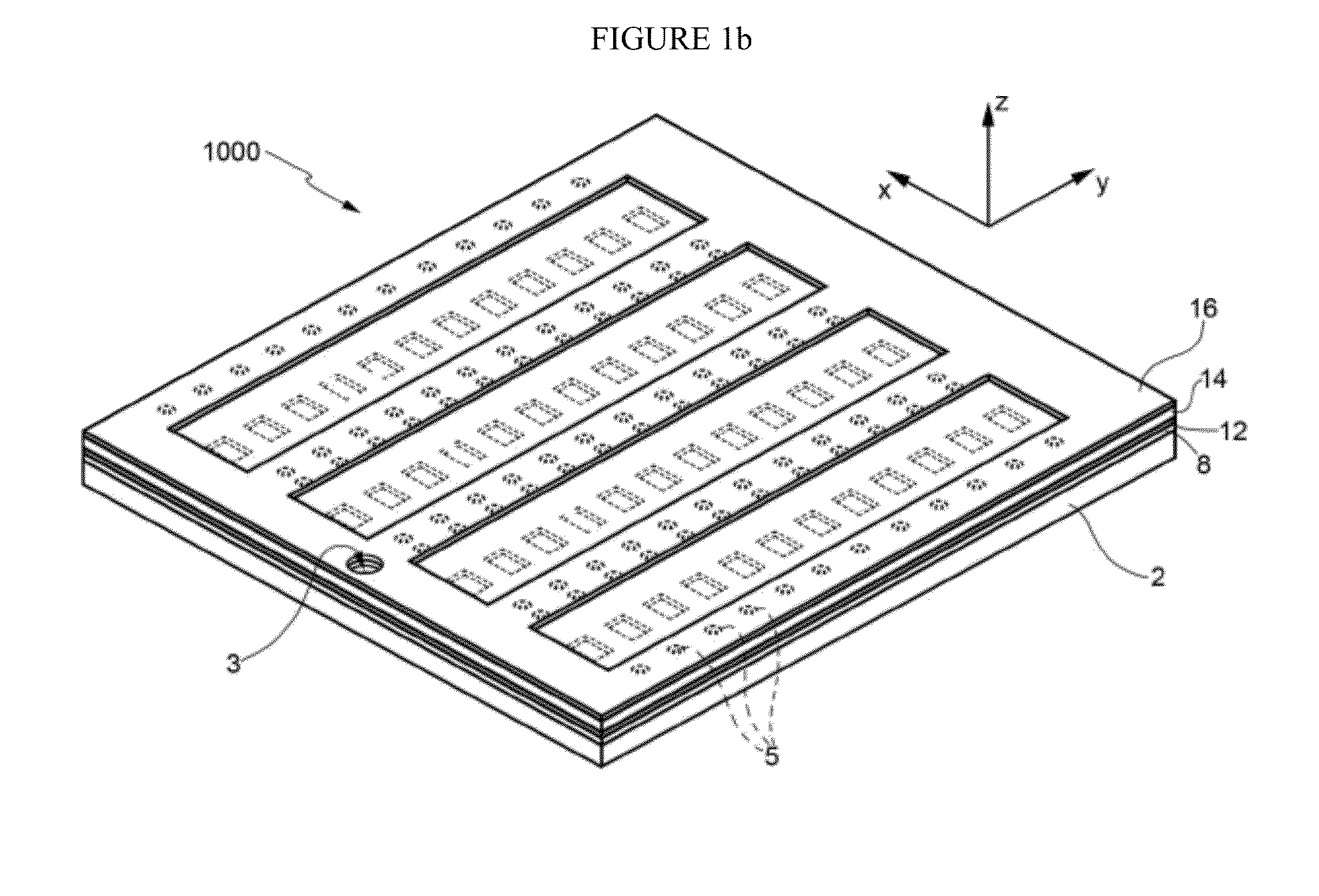
[0063]One embodiment herein described provides a microfluidic device comprising a body (e.g., semiconductor body that can be processed according to known MEMS manufacturing techniques) having a first side and a second side opposite to one another, and having on the first side of the body: at least a couple of wells or chambers adapted to store a fluid or a liquid; an inlet region forming an entrance point for the fluid or liquid to be supplied to the wells; a main channel fluidically connected to the inlet region; and at least a couple of secondary channels fluidically connecting the main channel to a respective well.

[0064]The wells extend within the body for a first depth, the main channel extends within the body for a second depth, the secondary channels extend within the body for a third depth, the first depth being greater than the second depth, and the second depth being greater than the third depth. The multi-level channels and chambers thus provide for a reduced contamination...


PUM

PropertyMeasurementUnit
thicknessaaaaaaaaaa
thicknessaaaaaaaaaa
thicknessaaaaaaaaaa

Abstract

A microfluidic device (1000-1005), comprising: a semiconductor body (2) having a first side (2a) and a second side (2b) opposite to one another, and housing, at the first side, a plurality of wells (4), having a first depth; an inlet region (30) forming an entrance point for a fluid to be supplied to the wells; a main channel (6a) fluidically connected to the inlet region, and having a second depth; and a plurality of secondary channels (6b) fluidically connecting the main channel to a respective well, and having a third depth. The first depth is higher than the second depth, which in turn is higher than the third depth. According to an aspect, the microfluidic device further comprises a cover layer (8), arranged above the first side of the semiconductor body, configured for sealing the wells and provided with at least a first valve hole (54) which extends through the cover layer and overlaps, at least partially, the secondary channels; and a flexible layer (14), arranged above the cover layer and provided with at least a protrusion (74) extending through the first valve hole towards the semiconductor body and overlapping, at least partially, the secondary channels, the flexible layer being configured such that, when a pressure is applied on it, the protrusion contacts the semiconductor body and enters the secondary channels thus fluidically isolating the wells from one another.

Description

PRIOR RELATED APPLICATIONS[0001]This application claims priority to Italian Application Number TO2012A000703, filed Aug. 3, 2012 and incorporated by reference in its entirety herein.FEDERALLY SPONSORED RESEARCH STATEMENT[0002]Not applicable.FIELD OF THE DISCLOSURE[0003]The present disclosure relates to a disposable microfluidic device, in particular to a disposable device, or platform, for multiplex parallel real time amplification such as PCR (Polymerase Chain Reaction).BACKGROUND OF THE DISCLOSURE[0004]Polymerase Chain Reaction, or PCR, allows an initial amount of DNA in a suitable reaction mix to be copied many times, thus increasing the amount of that DNA in the sample. PCR consists of repeated cycles of a denaturing phase wherein the DNA double helix is separated, an annealing phase wherein primers bind to the DNA target, and an extension phase wherein the primers are elongated by DNA polymerase, thus selectively amplifying the target DNA.[0005]Real time quantitative PCR (qPCR)...

Claims


Application Information

Patent Timeline
Patent Type & Authority Applications(United States)
IPC IPC(8): C12Q1/68
CPCC12Q1/686B01L3/5027B01L2300/0816B01L2300/0864
Inventor SPOTO, GIUSEPPE EMANUELEOCCHIPINTI, LUIGI GIUSEPPEDALL'OGLIO, CRISTIANRENNA, CROCIFISSO MARCO ANTONIODRAZEK, LAURENT
Owner STMICROELECTRONICS SRL
Why Eureka
Try Eureka