Control method for an internal combustion engine and internal combustion engine

a control method and internal combustion engine technology, applied in electrical control, output power, fuel injection apparatus, etc., can solve the problems of high smoke emissions, achieve the effects of reducing nox emissions, reducing smoke emissions, and reducing emissions

Active Publication Date: 2014-02-13
WARTSILA FINLAND OY
View PDF53 Cites 6 Cited by
  • Summary
  • Abstract
  • Description
  • Claims
  • Application Information

AI Technical Summary

Benefits of technology

[0009]The invention has several advantages. The Miller cycle is effective in reducing NOx emissions and controlling firing pressure at high loads, but leads to higher smoke emissions. According to the invention, the Miller cycle is utilized only when its benefits outweigh the drawbacks. The use of different fuel injection means for different amounts of fuel together with the selective use of the Miller cycle gives very low smoke emissions, while also the NOx emissions and SFOC can be minimized and exhaust temperature optimized.
[0010]According to an embodiment of the invention, the method comprises a third operating mode, in which mode conventional intake valve closing timing is used and fuel is injected using the first fuel injection means. This operating mode can be used at part load. Because of the conventional intake valve closing timing the smoke emissions can be kept low. With the first fuel injection means sufficient amount of fuel can be injected into the cylinder.
[0011]According to an embodiment of the invention, the method comprises a fourth operating mode, in which mode the Miller cycle is used and fuel is injected using the second fuel injection means. In this operating mode, very low NOx emissions can be achieved at relatively low loads. Also the temperature after the turbine of the turbocharger can be increased significantly, which enables selective catalytic reduction.
[0012]According to an embodiment of the invention, in the fourth operating mode later intake valve closing timing is used than in the first operating mode. According to an embodiment of the invention, the intake valve is closed 5-15 degrees of crank angle later. At high loads, earlier intake valve closing helps to lower SFOC and NOx emissions.
[0013]According to an embodiment of the invention, the method comprises a fifth operating mode, in which mode the Miller cycle with later intake valve closing timing than in the first operating mode is used and fuel is injected using the first fuel injection means. According to an embodiment of the invention, the intake valve is closed 5-15 degrees of crank angle later. With this operating mode, low SFOC can be achieved at medium to high engine loads together with relatively low NOx and smoke emissions.
[0014]According to an embodiment of the invention, in the first operating mode earlier intake valve opening timing is used than in the other operating modes. Earlier intake valve opening reduces the surging risk of the turbocharger when the Miller cycle with very early intake valve closing is used. According to an embodiment of the invention, in the first operating mode the intake valve is opened 10-30 degrees earlier than in the other operating modes.

Problems solved by technology

The Miller cycle is effective in reducing NOx emissions and controlling firing pressure at high loads, but leads to higher smoke emissions.

Method used


Image

  • Control method for an internal combustion engine and internal combustion engine
  • Control method for an internal combustion engine and internal combustion engine
  • Control method for an internal combustion engine and internal combustion engine

Examples


second embodiment

[0028]According to the invention, the method comprises a third operating mode that is used at part loads, as shown in table 2. In the embodiment of table 2, the third operating mode is used at loads that are 35-50% of the maximum load. Accordingly, the first operating mode is used at loads that are 50-100% of the maximum load, i.e. from intermediate to high loads.

TABLE 2Control strategy according to a second embodiment of the invention.Engine load0-35%35-50%50-100%2. mode3. mode1. modeValve timingNo MillerMiller cycleInjection needleSmall needleLarge needle

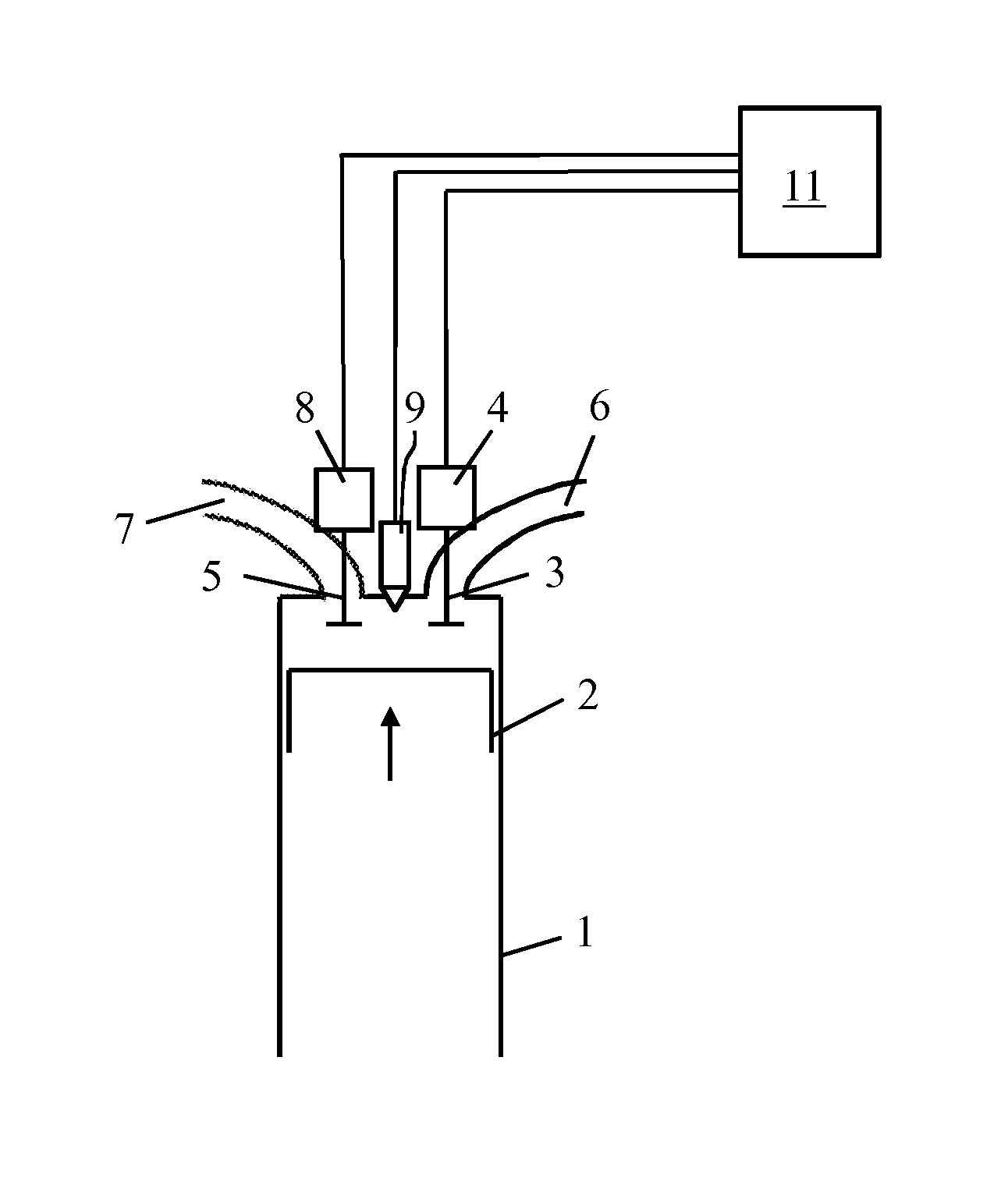
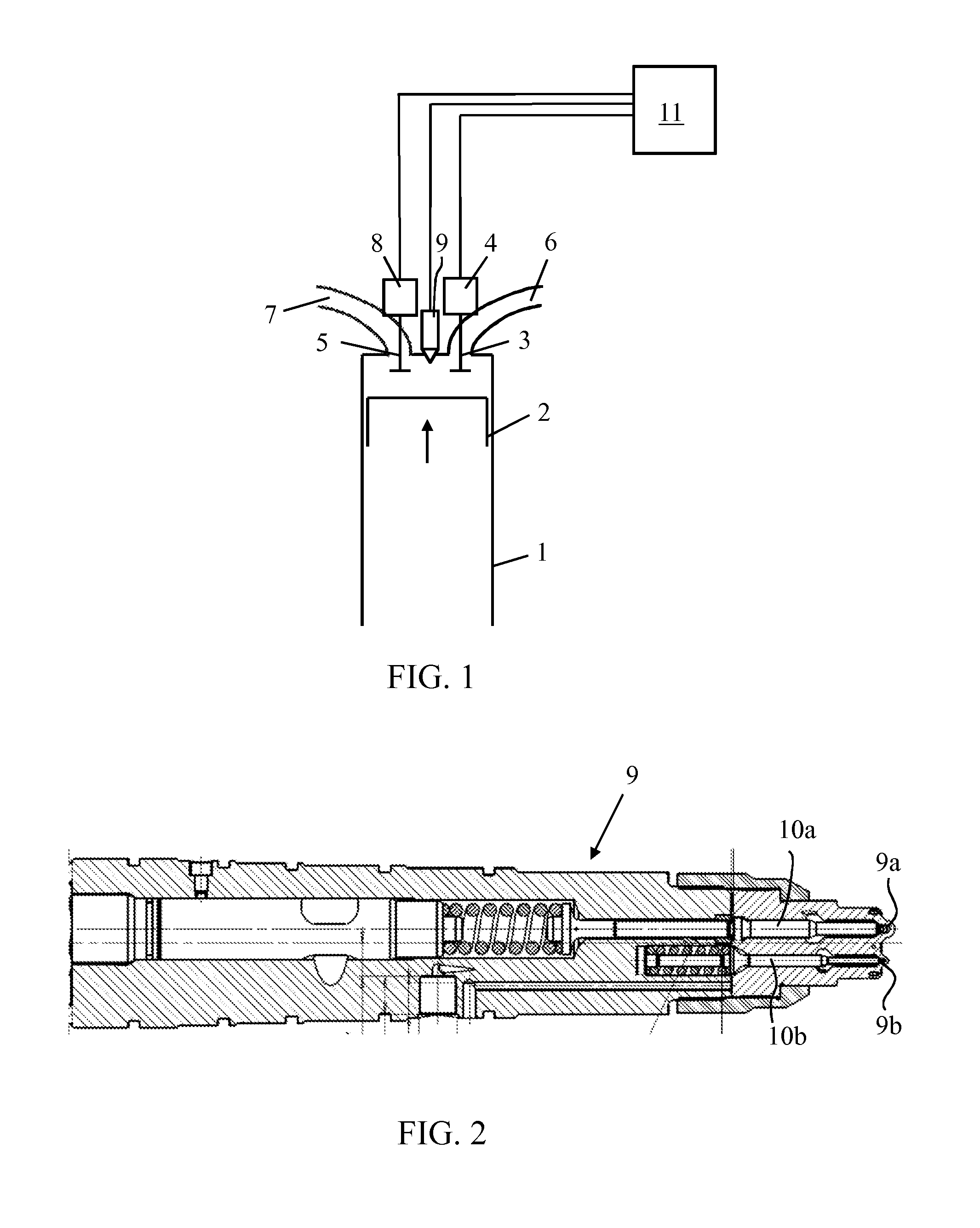
[0029]In the third operating mode, the Miller cycle is not used. Instead, conventional intake valve closing timing is used for achieving low smoke emissions. Fuel is injected into the cylinders 1 of the engine by using the first nozzle 9a.

third embodiment

[0030]According to the invention, the method comprises a fourth operating mode that is used at low loads, as shown in table 3. In the embodiment of table 3, the fourth operating mode is used at loads that are 15-35% of the maximum load. Accordingly, the second operating mode is used at loads that are 0-15% of the maximum load, i.e. at very low loads.

TABLE 3Control strategy according to a third embodiment of the invention.Engine load0-15%15-35%35-50%50-100%2. mode4. mode3. mode1. modeValve timingNo MillerMiller cycleInjection needleSmall needleLarge needle

[0031]In the fourth operating mode, fuel is injected into the cylinders 1 of the engine by using the second nozzle 9b for achieving low smoke emissions. The Miller cycle is used for achieving low NOx emissions.

fourth embodiment

[0032]According to the invention, the method comprises a fifth operating mode that is used at intermediate loads, as shown in table 4. In the embodiment of table 4, the fourth operating mode is used at loads that are 50-85% of the maximum load. Accordingly, the first operating mode is used at loads that are 85-100% of the maximum load, i.e. at high loads. The fifth operating mode gives low NOx emissions and SFOC at intermediate loads.

TABLE 4Control strategy according to a fourth embodiment of the invention.Engine load0-15%15-35%35-50%50-85%85-100%(very low)(low)(part)(intermediate)(high)2. mode4. mode3. mode5. mode1. modeVIC ONNo MillerInter. millerVIC OFFFull MillerVIO ONLong overlapInjection needleSmall needleLarge needle

[0033]Another difference between the embodiment of table 4 and the embodiments of tables 1-3 is that in the embodiment of table 4, the Miller cycle of the first operating mode is different from the Miller cycles of the other operating modes. In the fourth and fift...


PUM


Abstract

The method for controlling the operation of an internal combustion engine comprises at least two operating modes. In a first operating mode, the intake valve is closed at a first predetermined crank angle, in accordance with the Miller cycle, before the piston reaches bottom dead center during the intake stroke for reducing pressure in the cylinder, and fuel is injected using first fuel injection means optimized for large amounts of fuel. In a second operating mode the intake valve is closed at a second predetermined crank angle, in accordance with conventional intake valve closing timing, after or slightly before the piston has passed bottom dead center, and fuel is injected using second fuel injection means optimized for small amounts of fuel. The invention also concerns an internal combustion engine.

Description

TECHNICAL FIELD OF THE INVENTION[0001]The present invention relates to a method for controlling the operation of an internal combustion engine in accordance with the preamble of claim 1. The invention also concerns an internal combustion engine, as defined in the preamble of claim 13.BACKGROUND OF THE INVENTION[0002]In large compression ignition internal combustion engines, such as those used in ships or power plants, smoke formation at low loads is a common problem. The fuel injectors of the engines must be capable of delivering the fuel amount needed for the operation at maximum load. Since large internal combustion engines need to run reliably and efficiently at maximum or near maximum power, the injectors are even optimized for high loads. This means that at low loads the injectors do not work optimally and smoke is formed.[0003]The problem has been solved in prior art solutions by using injectors with two needles. For instance, in European patent application EP 0972932 A1 is di...

Claims


Application Information

Patent Timeline
Patent Type & Authority Applications(United States)
IPC IPC(8): F02D41/32
CPCF02D41/32F02D13/02F02D41/0002F02D41/3017F02D41/3094F02D41/40F02M45/086F02M2200/44Y02T10/12Y02T10/40F02D13/0234F02D13/0269F02D41/30F02M45/08
Inventor TROBERG, MIKAELZUANIGH, LUCAWINTERSTELLER, ANTONHATTAR, CHRISTERRIZZETTO, GINODELNERI, DIEGO
Owner WARTSILA FINLAND OY
Why Eureka
Try Eureka