Touch-sensitive rotary switch

Active Publication Date: 2014-02-13
CHU CHING HSIUNG
View PDF4 Cites 41 Cited by
  • Summary
  • Abstract
  • Description
  • Claims
  • Application Information

AI Technical Summary

Benefits of technology

[0008]The primary object of the present invention is to provide a switch configured to be touched along a rotary path so as to turn on or off an external power source or adjust in steps the magnitude of power supplied from the external power source. The present invention is intended to improve the low control precision typical of the c

Problems solved by technology

However, the mechanical rotary switch described above is an analog control device with relatively low precision in control.
Moreover, the mechanical components of a mechanical rotary switch tend to get loose, malfunction, or become damaged after long-term

Method used


Image

  • Touch-sensitive rotary switch
  • Touch-sensitive rotary switch
  • Touch-sensitive rotary switch

Examples


Example

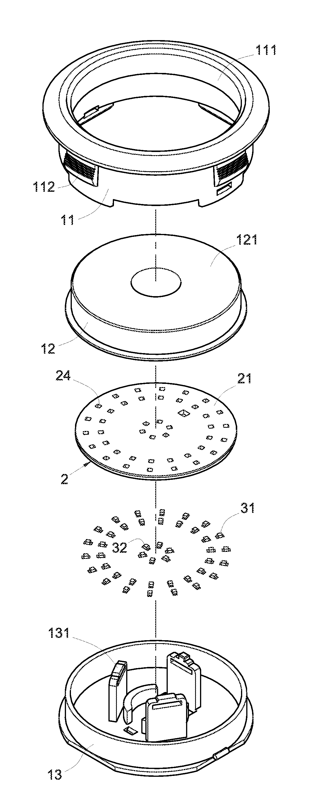
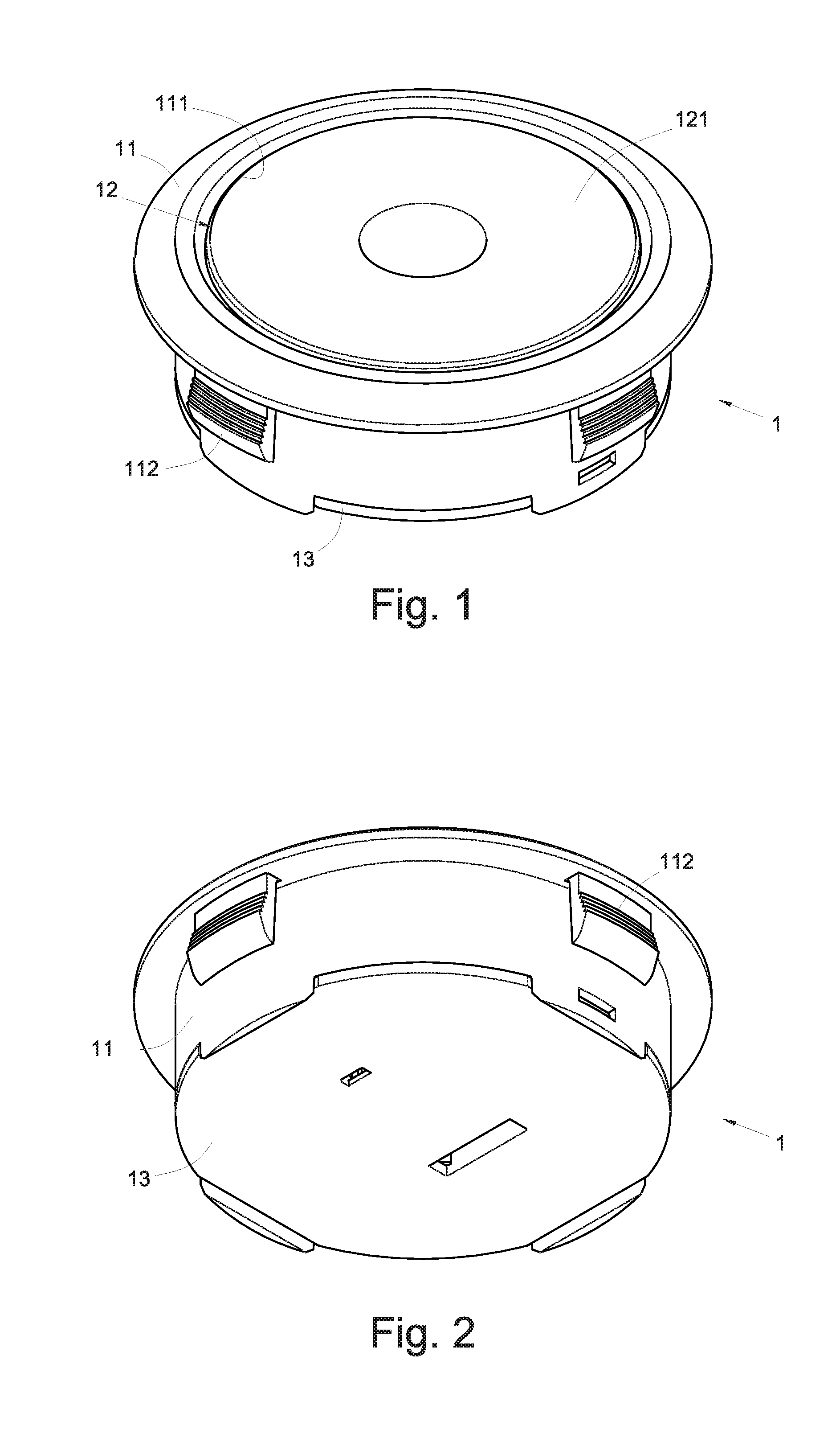
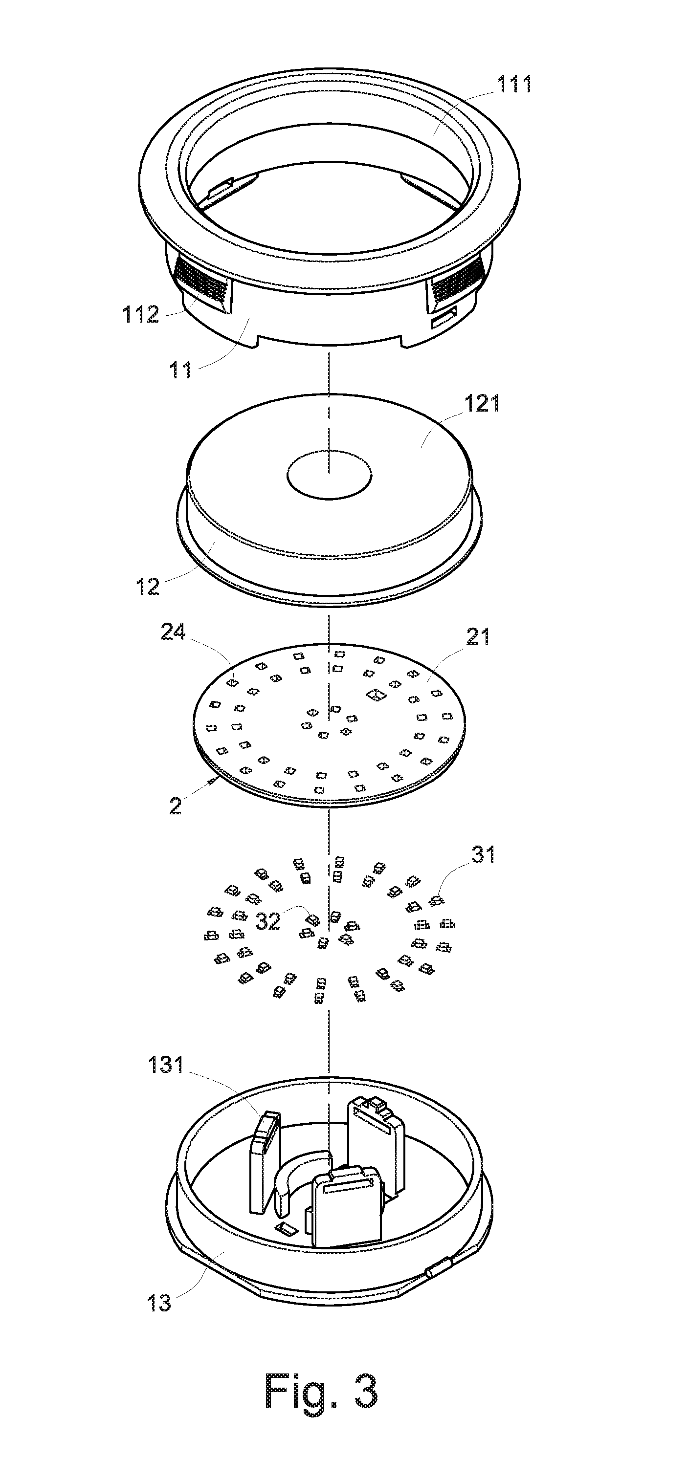
[0044]Please refer to FIG. 1 for a perspective view of a preferred embodiment of the present invention; FIG. 2 for a perspective bottom view of the embodiment depicted in FIG. 1; FIG. 3 for an exploded perspective view of the embodiment depicted in FIG. 1; FIG. 4 for a front view of the embodiment depicted in FIG. 1; FIG. 5 for a top view of the embodiment depicted in FIG. 4; FIG. 6 for a sectional view taken along line A-A of FIG. 5; FIG. 7 for a partial enlarged top view of FIG. 5; FIG. 8 for a top view similar to FIG. 5, illustrating a state of use; and

[0045]FIG. 9 for another top view similar to FIG. 5, illustrating another state of use. As shown in FIG. 1 through FIG. 9, the touch-sensitive rotary switch of the present invention includes a housing 1, a touch control circuit board 2, and a plurality of first light-emitting elements 31.

[0046]The housing 1 forms a receiving chamber 10 therein and has a top portion forming a sensing surface 121 to be touched by a human hand.

[0047]T...


PUM


Abstract

A touch-sensitive rotary switch is configured to be touched along a rotary path, thereby turning on or off, or adjusting stepwise the magnitude of power supplied from, an external power source. The rotary switch includes a housing whose top portion has a sensing surface. A touch control circuit board is provided in the housing and topped with a touch control circuit layer whose peripheral region is divided into multiple sensing areas in which plural first light-emitting elements are annularly arranged. The sensing areas can be sequentially triggered by touching the sensing surface along its peripheral region, so as for the corresponding portion of the touch control circuit layer to control light emission of the first light-emitting elements corresponding to the triggered sensing areas and to output a coded signal according to the triggered sensing areas in order to control the power supplied from the external power source.

Description

BACKGROUND OF THE INVENTION[0001]1. Technical Field[0002]The present invention relates to a touch-sensitive rotary switch and, more particularly, to a switch configured to be touched along a rotary path so as to turn on or off, or adjust stepwise the magnitude of power supplied from, an external power source.[0003]2. Description of Related Art[0004]Consumer electronics such as computers, communication devices, and home appliances are often equipped with rotary switches. Typically, a rotary switch is used to switch on or off a power source or adjust the magnitude of power supplied therefrom, thereby adjusting the operation speed or output power of an electric appliance powered by the power source. For example, a rotary switch may be used to adjust the rotation speed of an electric fan, the coolness of an air conditioner, the acoustic volume of a loudspeaker, the signal strength of a radio, and so forth.[0005]As is well known, most rotary switches are composed of mechanical structures...

Claims


Application Information

Patent Timeline
IPC IPC(8): H01H9/00
CPCH03K17/9622H03K17/9647H03K2217/96066H03K2217/960785
Inventor CHU, CHING-HSIUNG
Owner CHU CHING HSIUNG
Why Eureka
Try Eureka