Revolvingly spraying device

a rotating spraying device and spraying gun technology, applied in the direction of spraying nozzles, spraying apparatuses, moving spraying apparatuses, etc., can solve the problems of large number of components required, easy to have problems with the structure strength of spraying guns, and difficult assembly of spraying guns, etc., to achieve strong structure for stab spraying, easy manufacturing, and cost saving

Active Publication Date: 2014-02-13
STRONG FORTRESS TOOL
View PDF7 Cites 0 Cited by
  • Summary
  • Abstract
  • Description
  • Claims
  • Application Information

AI Technical Summary

Benefits of technology

[0016]By means of technical means of the present invention, the revolvingly spraying device is assembled with fewer component parts. Most components, each with multiple functions, are formed integrately with each other to achieve the goal of easy manufacture of the revolvingly spraying device and cost saving in production. Nevertheless it still makes the revolvingly spraying device have a stronger structure for stably spraying while being revolved.

Problems solved by technology

However, a large number of component parts are required in a conventional spraying gun for achieving the above revolving function when spraying fluid.
It not only makes difficult in assembling of the spraying gun but also easily has problems about structure strength of the spraying gun.
Moreover, the conventional spraying gun is also costly in production and thus it loses its market competitiveness due to these complex component parts.

Method used


Image

  • Revolvingly spraying device
  • Revolvingly spraying device
  • Revolvingly spraying device

Examples


Embodiment Construction

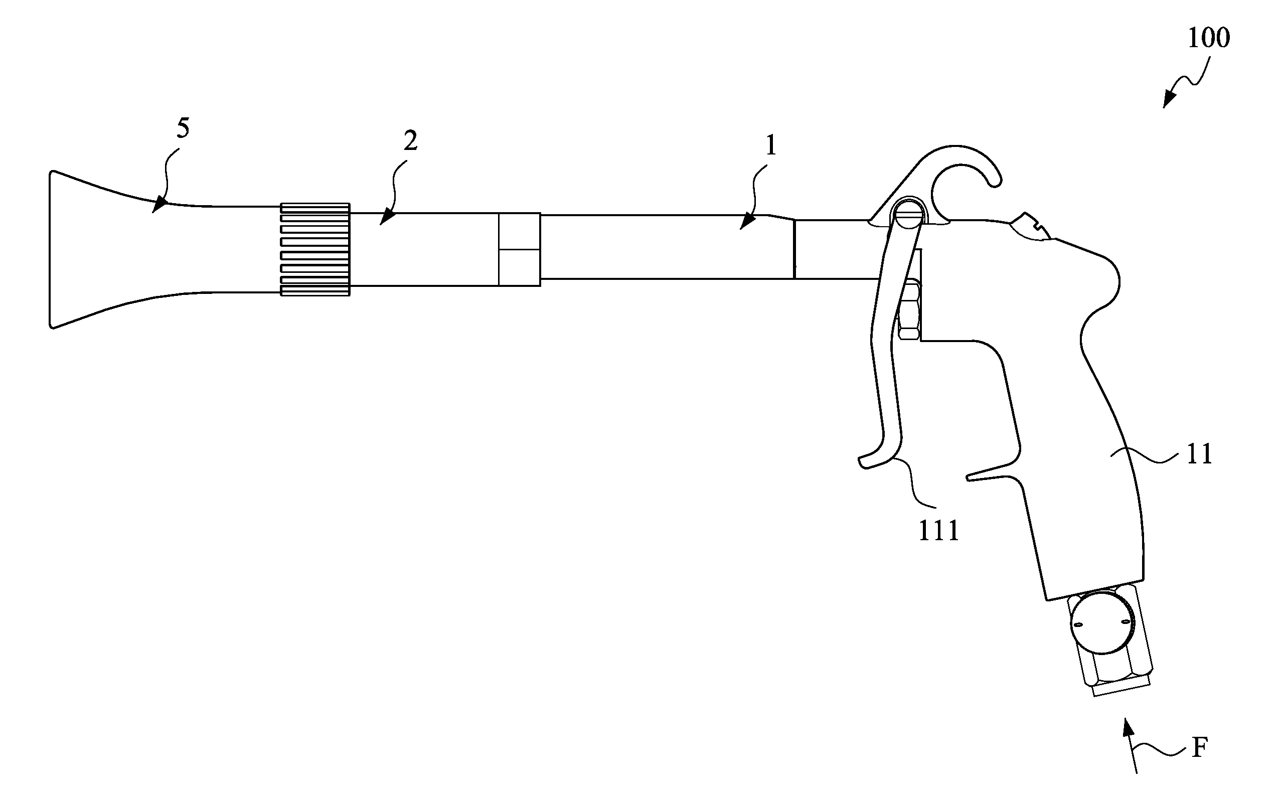
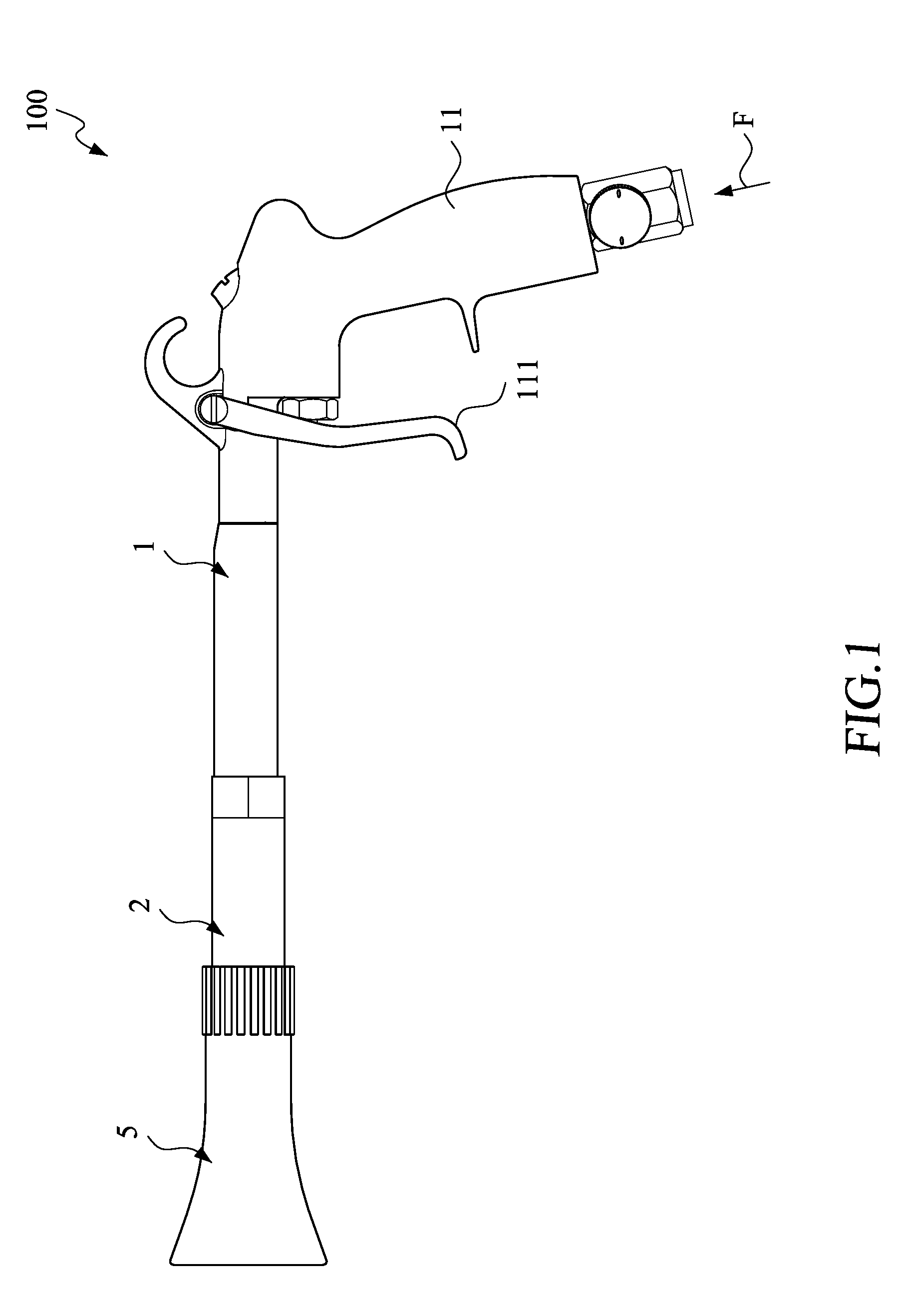
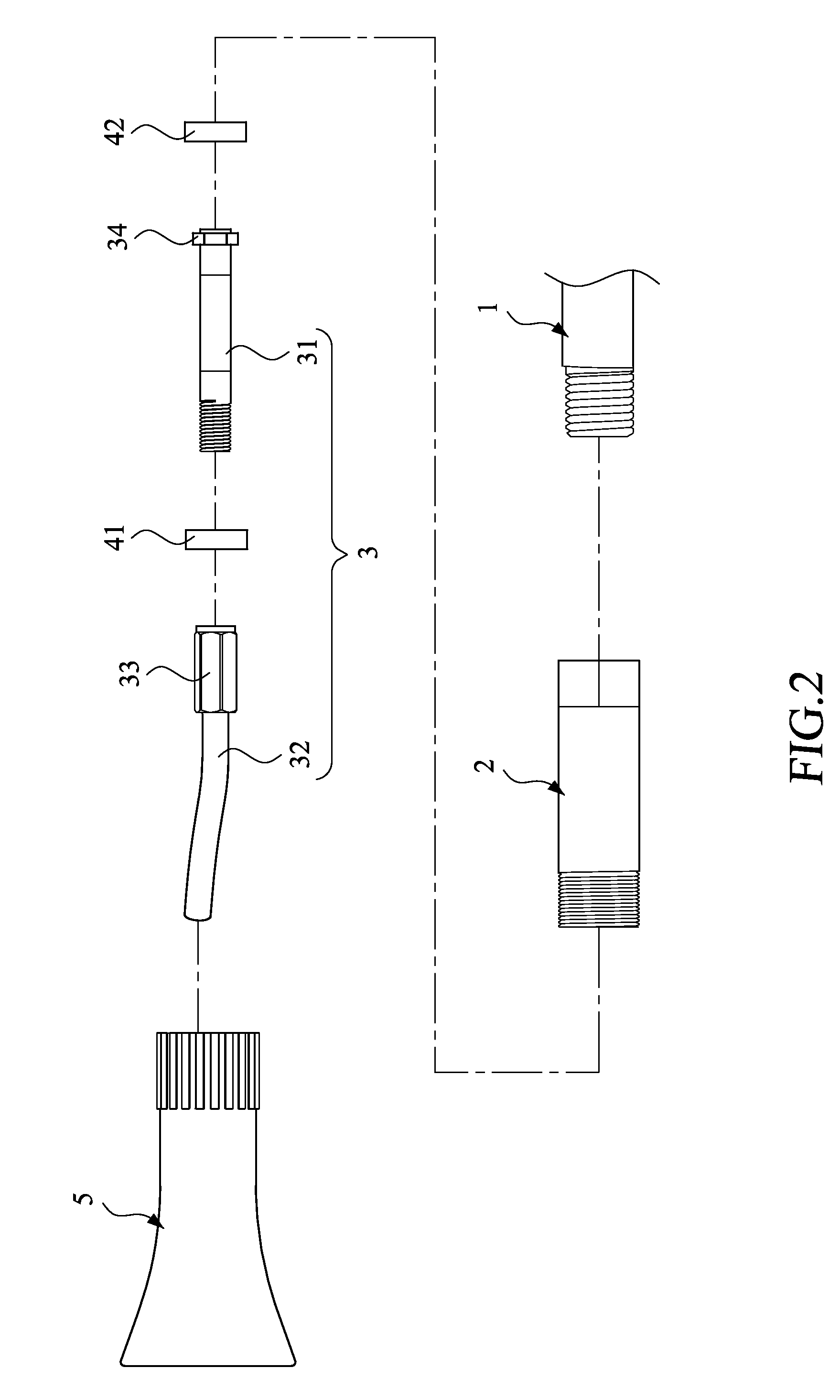
[0023]Please refer to FIGS. 1-4. FIG. 1 is a side view of a revolvingly spraying device according to an embodiment of the present invention, FIG. 2 is a explosion diagram showing the revolvingly spraying device of FIG. 1, FIG. 3 is a partial cross-section view of the revolvingly spraying device of FIG. 1, and FIG. 4 is a partial enlarged view of the revolvingly spraying device of FIG. 3.

[0024]As shown in FIGS. 1-4, a revolvingly spraying device 100 according to an embodiment of the present invention includes a spraying device body 1, a sheath tube 2, and a revolvingly spraying tube 3.

[0025]The spraying device body 1 is used for connecting to a fluid source (not shown) for receiving fluid. In this embodiment, the spraying device body 1 includes a control handle 11 provided with an adjusting means 111. The adjusting means 111, functions as a valve, can be used to adjust the flow rate of a fluid F flowing from the fluid source to the spraying device body 1.

[0026]The sheath tube 2, whic...


PUM


Abstract

A revolvingly spraying device includes a sheath tube and a revolvingly spraying tube. The revolvingly spraying tube includes a transmitting tube and a curved tube connected with the transmitting tube. The transmitting tube is inserted within the sheath tube. A front bearing is provided in one end, near the curved tube, of the transmitting tube, and a rear bearing is provided in the other end of the transmitting tube. The revolvingly spraying tube has a front position limiting portion radially protruding therefrom to retain the front side of the front bearing, and a rear position limiting portion radially protruding therefrom to retain the rear side of the rear bearing. Thus, the revolvingly spraying device has fewer component parts and is convenient for assembly.

Description

FIELD OF THE INVENTION[0001]The present invention relates to a spraying gun, and more particularly to a revolvingly spraying device for revolvingly spraying fluid.BACKGROUND OF THE INVENTION[0002]There are many conventional spraying guns used widely for cleaning dust and dirt from a surface of an object, for watering, for spraying paint, and the like. The spraying guns remove dust and dirt by spraying a high pressure fluid, and perform watering and spraying paint with the use of a high pressure fluid mixed with water or other spraying liquid.[0003]In order to uniform the distribution of the spraying, a spraying tube of the spraying gun is usually bended curve and is assembled with a rotary means, so that a mixed fluid of a high pressured gas and a spraying liquid can be sprayed out in every direction while rotating the spraying tube.SUMMARY OF THE INVENTION[0004]However, a large number of component parts are required in a conventional spraying gun for achieving the above revolving f...

Claims


Application Information

Patent Timeline
Patent Type & Authority Applications(United States)
IPC IPC(8): B05B9/01B05B1/34
CPCB05B1/28B05B3/0409B05B7/0869B05B3/06B05B7/2435
Inventor HUANG, SU YENHSU, TZU AN
Owner STRONG FORTRESS TOOL
Why Eureka
Try Eureka