
Variable magnification optical system and imaging apparatus

a magnification optical system and variable magnification technology, applied in the field of variable magnification optical system and imaging apparatus, can solve the problems of insufficient zoom ratio, too large f-number to be used with monitoring cameras, etc., and achieve high optical performance, high zoom ratio, and high aperture ratio

Inactive Publication Date: 2014-02-13
FUJIFILM CORP
View PDF4 Cites 11 Cited by
  • Summary
  • Abstract
  • Description
  • Claims
  • Application Information

AI Technical Summary

Benefits of technology

The present invention is a variable magnification optical system that is compact, has high aperture ratio and high zoom ratio, and keeps high optical performance that allows obtaining high-quality images over a wide wavelength band from the visible range to the near-infrared range. The optical system includes a negative first lens group and a positive second lens group, which can change magnification by changing the interval between the first lens group and the second lens group in the optical axis direction, and the position of the first lens group in the optical axis direction. The lens configuration of the second lens group is set in detail to achieve high optical performance. The imaging apparatus provided with the variable magnification optical system is compact, can take images even under a low illumination condition, has high magnifying power, and can obtain good images over a wide wavelength band from the visible range to the near-infrared range.

Problems solved by technology

However, the optical system disclosed in Patent Document 2 is a zoom lens for use with single-lens reflex cameras, which has a f-number that is too large to be used with monitoring cameras and therefore is not deemed to have a high aperture ratio.
The optical system disclosed in Patent Document 3 is a projection lens, which has a f-number that is too large to be used with monitoring cameras and has insufficient zoom ratio.

Method used


Image

  • Variable magnification optical system and imaging apparatus
  • Variable magnification optical system and imaging apparatus
  • Variable magnification optical system and imaging apparatus

Examples


Embodiment Construction

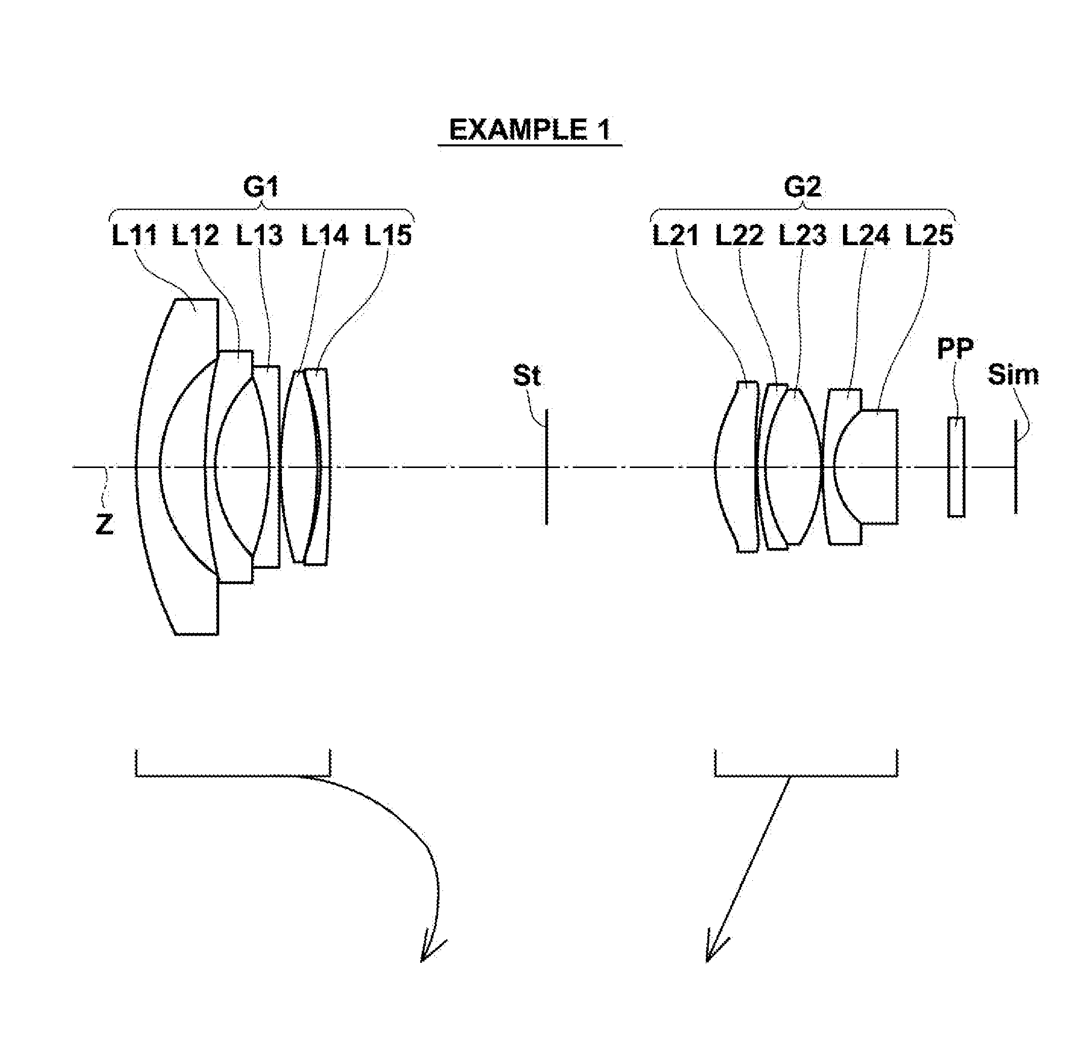
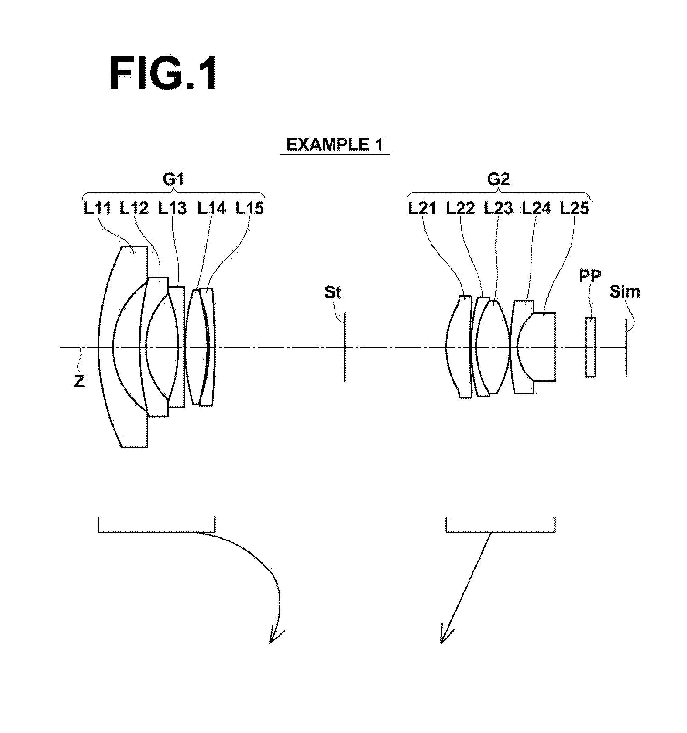
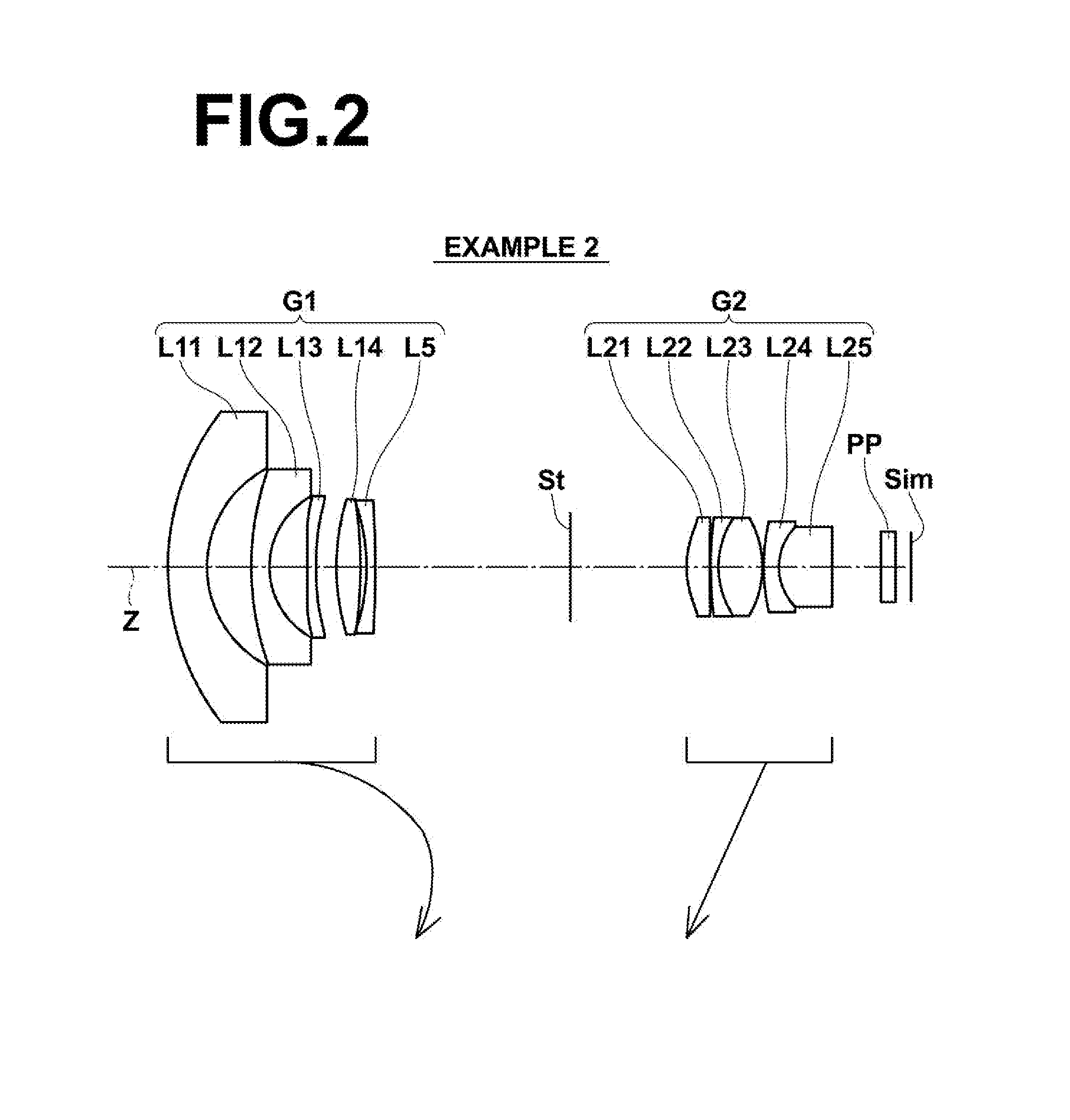
[0051]Hereinafter, embodiments of the present invention will be described in detail with reference to the drawings. FIG. 1 is a sectional view illustrating a configuration example of a variable magnification optical system according to an embodiment of the invention and corresponds to a variable magnification optical system of Example 1, which will be described later. FIGS. 2 to 8 are sectional views illustrating other configuration examples according to the embodiment of the invention and correspond to variable magnification optical systems of Examples 2 to 8, respectively, which will be described later. The examples shown in FIGS. 1 to 8 has the same basic configuration and are shown in the same manner in the drawings. Therefore, the variable magnification optical system according to the embodiment of the invention is described mainly with reference to FIG. 1.

[0052]This variable magnification optical system includes, in order from the object side, a first lens group G1 having a ne...


PUM


Abstract

A variable magnification optical system includes, in order from the object side, a negative first lens group and a positive second lens group, wherein the interval between these lens groups in the optical axis direction is changed during magnification change. The most image-side lens and the second most image-side lens of the first lens group are a negative single lens with a concave surface facing the object side and a positive single lens, respectively. The second lens group includes, in order from the object side, a positive lens disposed at the most object-side position with at least one surface thereof being an aspherical surface, a first cemented lens formed by a negative lens and a positive lens, and a second cemented lens formed by a negative lens and a positive lens.

Description

CROSS REFERENCE TO RELATED APPLICATIONS[0001]This application is a Bypass continuation of PCT / JP2012 / 002983 filed on May 7, 2012, which claims foreign priority to Japanese Application No. 2011-104128 filed on May 9, 2011. The entire contents of each of the above applications are hereby incorporated by reference.TECHNICAL FIELD[0002]The present invention relates to a variable magnification optical system for use with video cameras, electronic still cameras, etc., and to an imaging apparatus. More particularly, the present invention relates to a variable magnification optical system that is suitable for use with monitoring cameras and is usable in a wide wavelength range from the visible range to the near-infrared range, and to an imaging apparatus provided with the variable magnification optical system.BACKGROUND ART[0003]Conventionally, monitoring cameras are used for the purpose of security, recording, etc. It is required for an optical system for use with such a monitoring camera ...

Claims


Application Information

Patent Timeline
Patent Type & Authority Applications(United States)
IPC IPC(8): G02B13/04
CPCG02B13/04G02B13/14G02B13/18G02B15/177G02B15/143507H01L27/14625
Inventor TOMIOKA, UKYO
Owner FUJIFILM CORP
Learn More