
Plastic panels for motor vehicles and methods for making the same

Active Publication Date: 2014-02-13
FAURECIA INTERIOR SYST
View PDF1 Cites 4 Cited by
  • Summary
  • Abstract
  • Description
  • Claims
  • Application Information

AI Technical Summary

Benefits of technology

The patent text describes plastic panels for motor vehicles and methods for making them. The panels have a microcellular structured core with a support structure and are made by first molding a microcellular polymeric substrate with a first outer skin, a second outer skin, and a wall between them. A weld feature on a second polymeric substrate is aligned with the support structure of the first substrate and is welded onto it to attach the two substrates together. The technical effect of this invention is to provide a lightweight plastic panel with improved strength and durability for use in motor vehicles.

Problems solved by technology

Unfortunately, welding two or more plastic substrates together when one or more of the plastic substrates is a microcellular polymeric substrate can produce a plastic panel that has less robust and / or lower weld strength weld joints than traditional plastic panels that are formed from welding two or more solid plastic substrates together.
This can be problematic particularly in relatively high energy, high stress, and / or high impact plastic panel applications, e.g., instrument panels with integrated airbag systems, knee bolsters, and the like, where robust and / or higher weld strength weld joints may be needed to avoid partial or full delamination of the plastic substrates.
Unfortunately, the guide portions do not effectively increase the welding pressure along the welding surfaces in cases where one or both of the plastic parts have a relatively compliant core that compresses in response to the applied welding pressure, e.g., microcellular polymeric substrate.
Unfortunately, this is not always practical because package space is often limited in many applications and increasing the welding surface area may not be a viable option.

Method used


Image

  • Plastic panels for motor vehicles and methods for making the same
  • Plastic panels for motor vehicles and methods for making the same
  • Plastic panels for motor vehicles and methods for making the same

Examples


Embodiment Construction

[0013]The following Detailed Description is merely exemplary in nature and is not intended to limit the various embodiments or the application and uses thereof. Furthermore, there is no intention to be bound by any theory presented in the preceding background or the following detailed description.

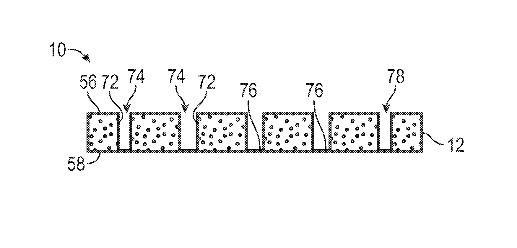
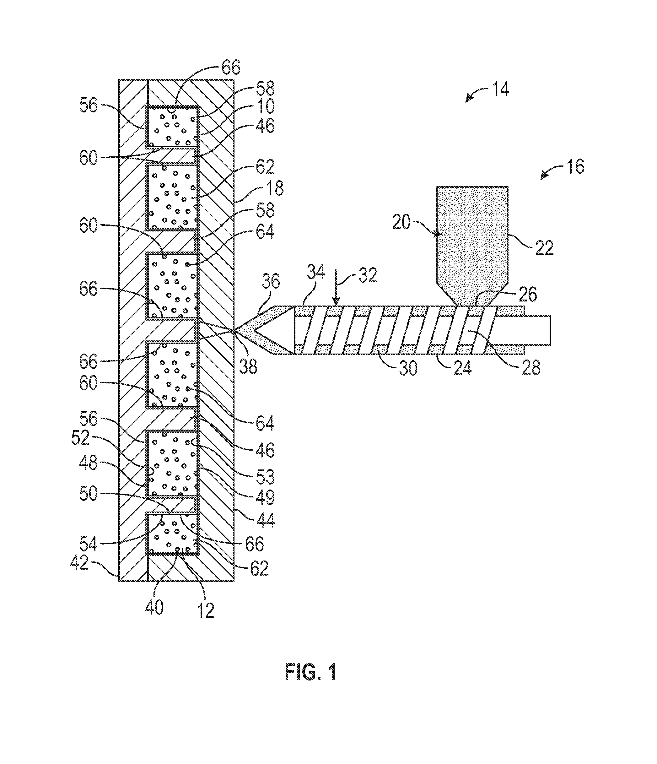
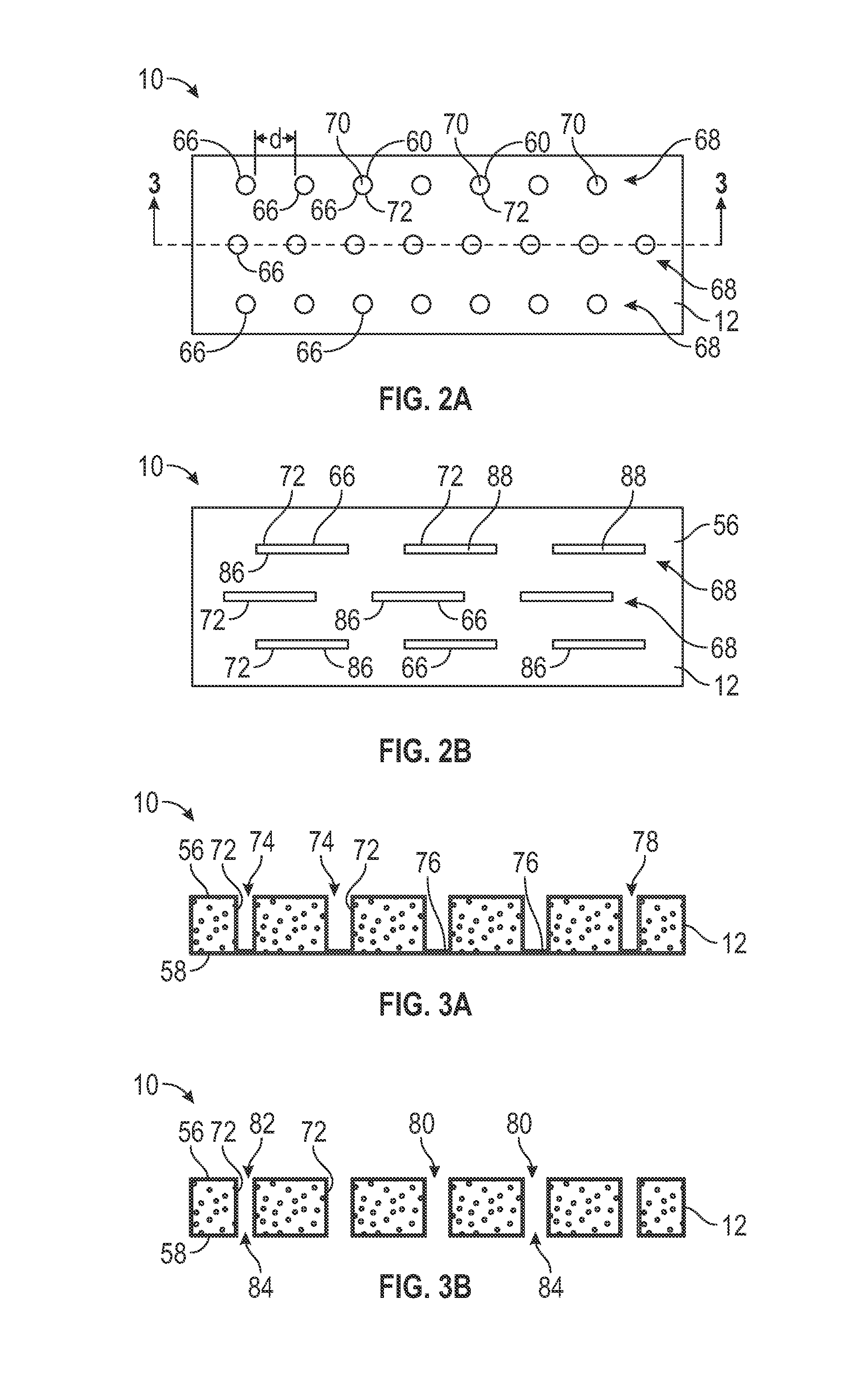
[0014]Various embodiments contemplated herein relate to plastic panels including welded polymeric substrates for motor vehicles, and methods for making such plastic panels. The exemplary embodiments taught herein provide a plastic panel for a motor vehicle comprising a first molded microcellular polymeric substrate and a second polymeric substrate. The first molded microcellular polymeric substrate is formed, for example, via injection molding or the like and has a first outer skin, a second outer skin, and a microcellular structured core that is disposed between the first and second outer skins. A wall extends substantially between the first and second outer skins and through the microcell...


PUM


Abstract

Plastic panels for motor vehicles and methods for making plastic panels are provided herein. In one example, a plastic panel for a motor vehicle comprises a first molded microcellular polymeric substrate and a second polymeric substrate. The first molded microcellular polymeric substrate has a first outer skin, a second outer skin, a microcellular structured core that is disposed between the first and second outer skins, and a wall that extends between the first and second outer skins to define a support structure in the microcellular structured core. The second polymeric substrate comprises a weld feature that is aligned with the support structure and that is coupled to the second outer skin of the first molded microcellular polymeric substrate.

Description

TECHNICAL FIELD[0001]The technical field relates generally to plastic panels for motor vehicles, and more particularly relates to plastic panels including welded polymeric substrates for motor vehicles and methods for making such plastic panels.BACKGROUND[0002]In the transportation industry, there is considerable impetus for the reduction of weight of vehicle components. In many cases, for example, the reductions in weight are necessary to achieve designated fuel economy standards that are becoming even more stringent. Alternative designs and / or constructions of many vehicle components are often considered particularly in the automotive sector as well as in other transportation industries if the resulting parts can achieve significant weight savings.[0003]Recently, some automakers have been exploring the use of microcellular foaming technologies for molding lighter weight plastic substrates for overall vehicle weight reduction and improved fuel economy. Plastic substrates that are f...

Claims


Application Information

Patent Timeline
IPC IPC(8): B32B3/28B32B3/26B32B5/20
CPCB29C65/02B29C65/06B29C65/08B29C66/301B29C66/3022B29C66/30223B29C66/532B29C66/54B29C66/727B29K2105/041B29L2031/3008B29L2031/3038B29L2031/3041B32B3/06B32B27/08B32B27/32B32B2605/00B60R13/02B60R21/215B60K37/00Y10T428/2457Y10T428/249976
Inventor TWORK, MICHAELKONIECZNY, THEODORE
Owner FAURECIA INTERIOR SYST
Learn More