Method of disposing catalyst in reformer

a technology of catalyst and reformer, which is applied in the direction of layered products, chemistry apparatus and processes, synthetic resin layered products, etc., can solve the problems of low power density, global warming and energy crisis, and the operation of dm

Inactive Publication Date: 2014-02-20
NATIONAL TSING HUA UNIVERSITY
View PDF5 Cites 0 Cited by
  • Summary
  • Abstract
  • Description
  • Claims
  • Application Information

AI Technical Summary

Benefits of technology

[0007]Therefore, it is a primary objective of the present invention to provide a method of disposing catalyst in a reformer to achieve the effect of increasing the gradient-thickness of catalysts in the channels and enhancing the H2 gas generating efficiency of the reformer.
[0024]The method of disposing catalyst in a reformer according to the present invention adopt a centrifugation to obtain a catalyst layer with a gradient-thickness on a wall of the pattern, so that the present invention has the following advantages:
[0025](1) The method of disposing catalyst in a reformer of the present invention can provide a catalyst layer with coarse and irregular surface so as to make the catalysts to react with methanol efficiently.
[0026](2) The method of disposing catalyst in a reformer of the present invention can provide a catalyst layer with gradient-thickness so as to make the catalysts to react with methanol completely.

Problems solved by technology

In recent years, the global warming and energy crisis have been an emerging issue around the world.
DMFC can be operated at lower temperature but supplies low power density.
The low power density of DMFC is because of methanol crossover through the membrane and the low reaction rate of methanol oxidation at anodic catalyst.
Yet, the slurry method may only coat a thin layer of catalysts in the channel, and the thin layer of catalysts would not sufficiently react with the methanol to generate H2 gas, which results in low efficiency of the reformer.
Moreover, the distribution pattern of the catalyst in the channels affects the efficiency of the reformer as well.
Conventionally, the distribution pattern of the catalysts is mostly circular shape, which may lead to non-uniform catalysts utilization.
Thus, how to maximize the efficiency of the reformer and the amount of catalysts coated in the channel has become the major issue in the art.

Method used


Image

  • Method of disposing catalyst in reformer
  • Method of disposing catalyst in reformer
  • Method of disposing catalyst in reformer

Examples


Embodiment Construction

[0034]The technical content of the present invention will become apparent by the detailed description of the following embodiments and the illustration of related drawings as follows.

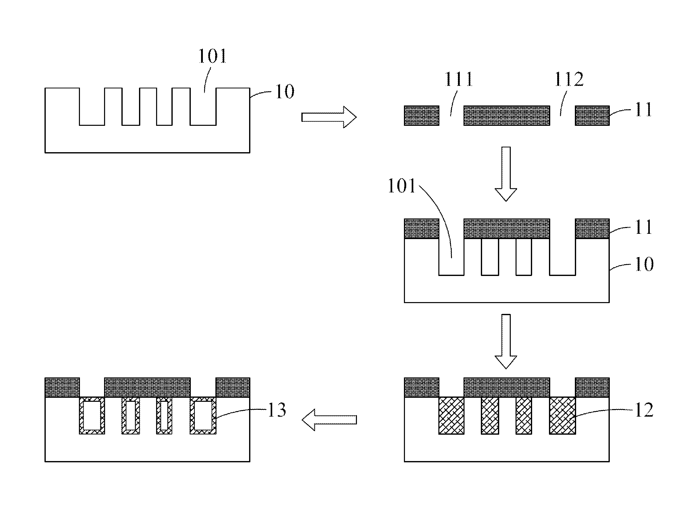
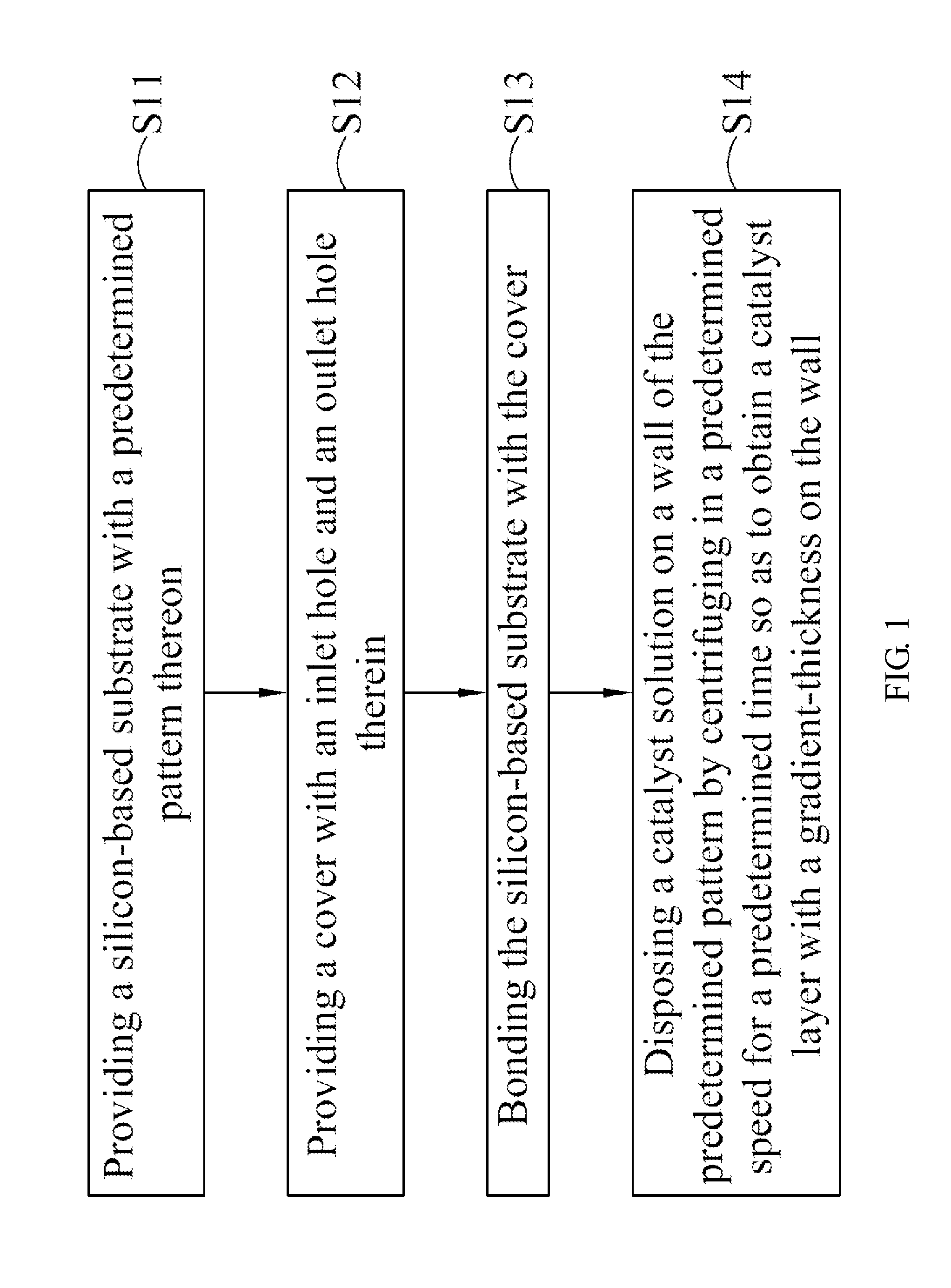
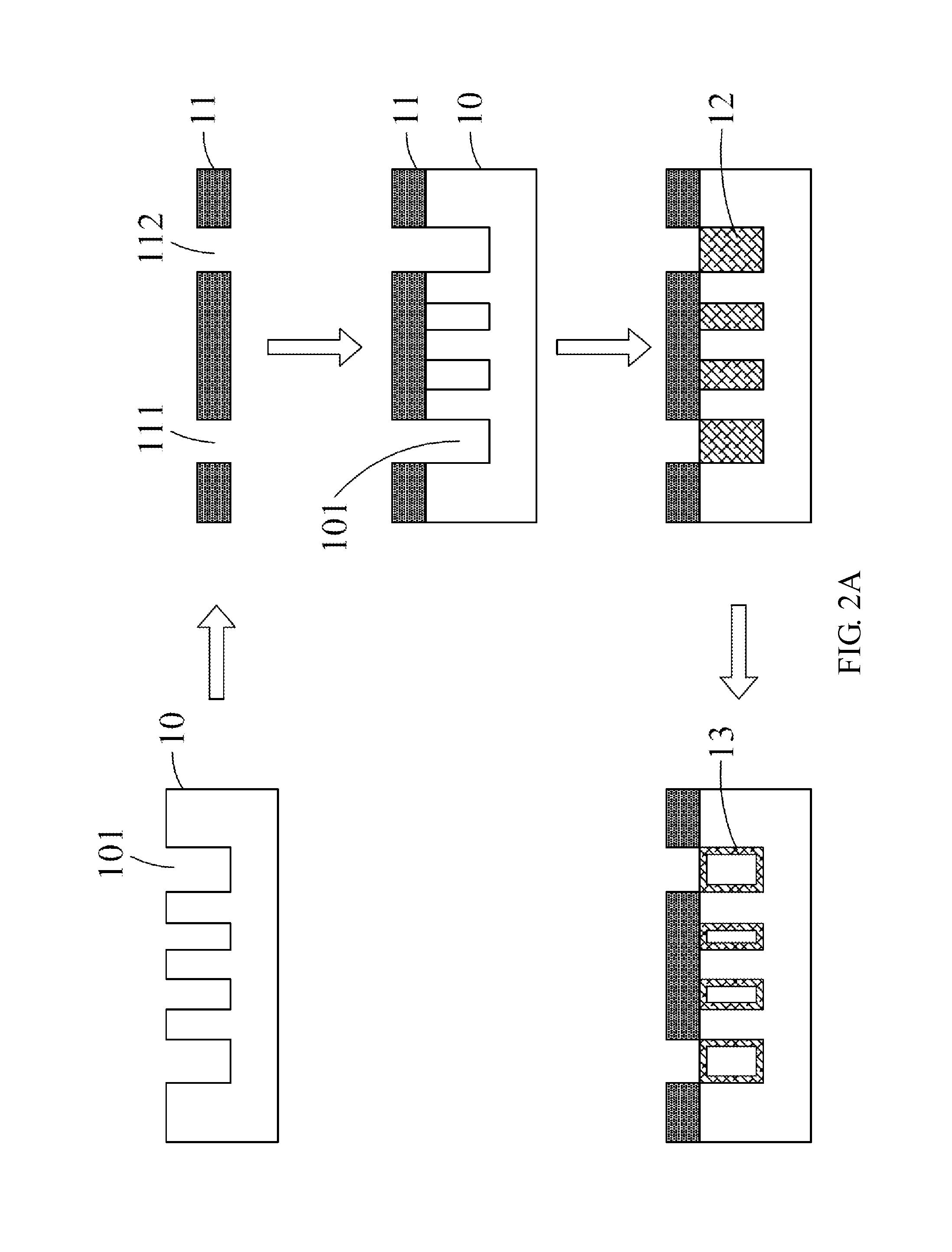
[0035]With reference to FIG. 1 and FIG. 2A, for a flow chart and a schematic view of a method of disposing catalyst in a reformer, respectively, in accordance with the present invention, the method of disposing catalyst in a reformer comprises steps of:

[0036]S11: providing a silicon-based substrate 10 with a predetermined pattern thereon;

[0037]S12: providing a cover 11 with an inlet hole 111 and an outlet hole 112 therein;

[0038]S13: bonding the silicon-based substrate 10 with the cover 11; and

[0039]S14: disposing a catalyst solution 12 on a wall of the predetermined pattern by centrifuging in a predetermined speed for a predetermined time so as to obtain a catalyst layer 13 with a gradient-thickness on the wall.

[0040]In a preferred embodiment, the gradient-thickness of the catalyst layer 13 is gradually...


PUM

PropertyMeasurementUnit
flow rateaaaaaaaaaa
thicknessaaaaaaaaaa
timeaaaaaaaaaa

Abstract

A method of disposing catalyst in a reformer is disclosed. The method of disposing catalyst comprises the steps of providing a silicon-based substrate with a predetermined pattern thereon; providing a cover with an inlet hole and an outlet hole therein; bonding the silicon-based substrate with the cover; and disposing a catalyst solution on a wall of the predetermined pattern by centrifuging in a predetermined speed for a predetermined time so as to obtain a catalyst layer with a gradient-thickness on the wall.

Description

BACKGROUND OF THE INVENTION[0001]1. Field of the Invention[0002]The present invention generally relates to a method of disposing catalyst, in particular to a method of disposing catalyst in reformer.[0003]2. Description of the Related Art[0004]In recent years, the global warming and energy crisis have been an emerging issue around the world. For this reason, it's necessary to develop green, clean and renewable energies to solve such problems. In varieties of eco-friendly methods to create energies, fuel cells have emerged advantageously as alternative power sources owing to their high overall system efficiency and eco-friendly nature. For instance, one of the attractive applications is the use of the fuel cells in portable electronics so that the fuel cells are becoming striking alternatives to conventional lithium ion batteries.[0005]There are mainly two types of small fuel cells can be used: direct methanol fuel cell (DMFC) and proton exchange membrane fuel cell (PEMFC). DMFC can ...

Claims


Application Information

Patent Timeline
Patent Type & Authority Applications(United States)
IPC IPC(8): B32B38/00
CPCB01J19/0093B01J2219/00783B01J2219/00828B01J2219/00831B01J2219/00835C01B3/40C01B2203/0233C01B2203/066C01B2203/067C01B2203/1035C01B2203/1223Y02E60/50
Inventor TSENG, FAN-GANGWANG, HSUEH-SHENG
Owner NATIONAL TSING HUA UNIVERSITY
Why Eureka
Try Eureka