Touch sensing unit and a liquid crystal display panel with the same

a touch sensing unit and liquid crystal display technology, applied in the field of touch panels, can solve the problem that the electric b>120/b> cannot be too large, and achieve the effect of improving the sensing accuracy of touch position

Inactive Publication Date: 2014-02-20
INNOLUX CORP
View PDF2 Cites 3 Cited by
  • Summary
  • Abstract
  • Description
  • Claims
  • Application Information

AI Technical Summary

Benefits of technology

[0011]An object of the present invention is to provide a touch sensing unit and a liquid crystal display panel with the same for effectively improving sensing accuracy of touch position.

Problems solved by technology

However, in actual application, when the touch sensing device 100 is integrated into a liquid crystal display panel, the actual detection electrode 120 cannot be too large due to the consideration of the aperture ratio of the liquid crystal display and the resolution and visual feeling of the liquid crystal display panel, meaning that the capacitance value Cf of the finger capacitor is approximately smaller than or equal to 1 fF.

Method used


Image

  • Touch sensing unit and a liquid crystal display panel with the same
  • Touch sensing unit and a liquid crystal display panel with the same
  • Touch sensing unit and a liquid crystal display panel with the same

Examples


Embodiment Construction

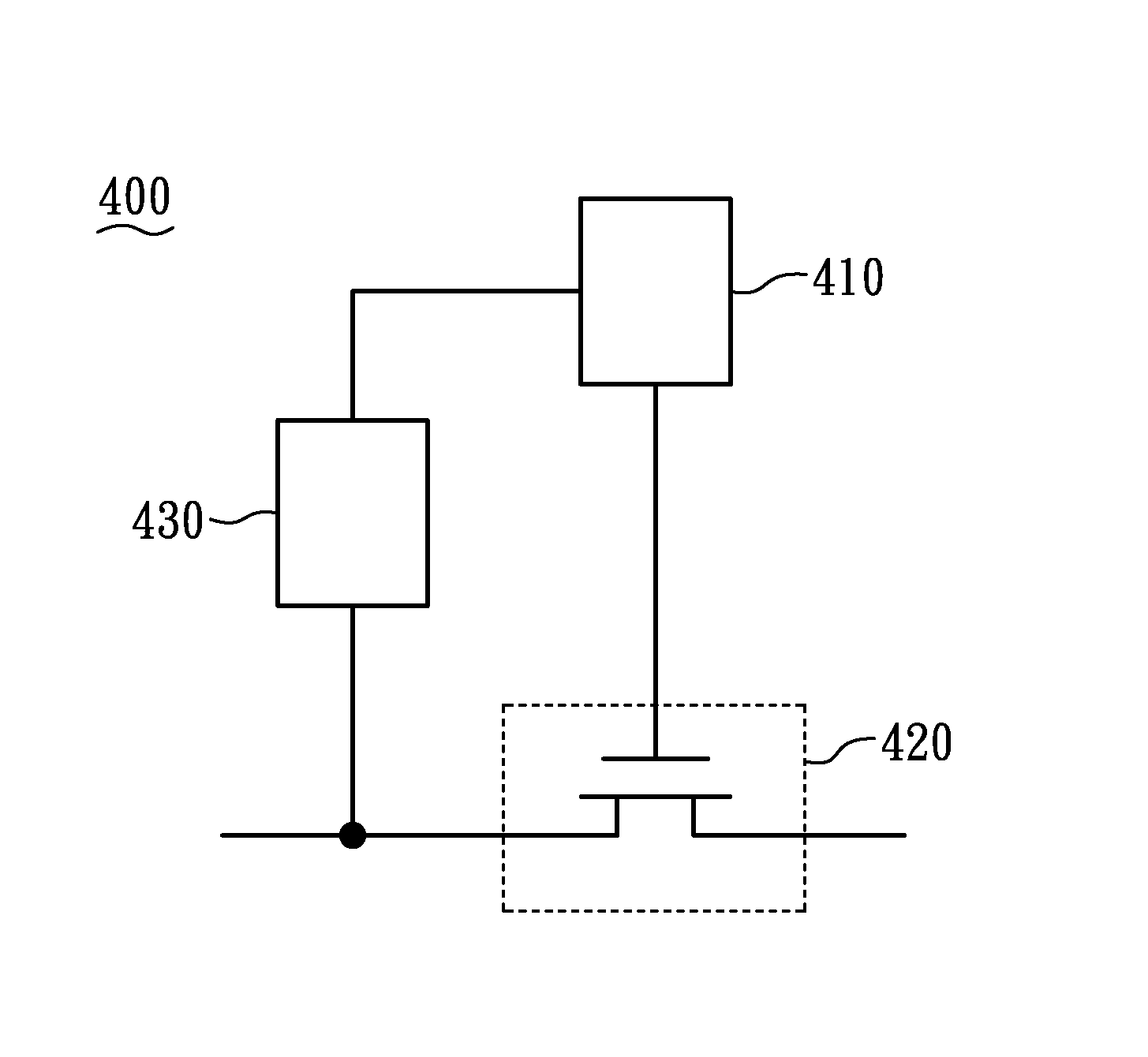
[0030]FIG. 4 is a schematic diagram of a touch sensing unit 400 of the present invention. The touch sensing unit comprises a detection electrode 410, a switch 420, a boosting and discharging unit 430 and a sensing control signal source 440.

[0031]The detection electrode 410 is provided for detecting a touch from an external object.

[0032]The switch 420 is connected to the detection electrode 410 for generating a detection voltage. The switch 420 is a first MOS transistor 420 having a gate connected to the detection electrode 410.

[0033]The boosting and discharging unit 430 is connected to the detection electrode 410 and the switch 420 for discharging the detection electrode 410 or boosting voltage of the detection electrode 410.

[0034]The sensing control signal source 440 is connected to the switch 420 for providing a discharging reference voltage or a sensing reference voltage, wherein the discharging reference voltage has a voltage level smaller than that of the sensing reference volt...


PUM


Abstract

A touch sensing unit includes a detection electrode, a switch and a boosting and discharging unit. The detection electrode detects the touch from an external object. The switch is connected to the detection electrode for generating a touch voltage. The boosting and discharging unit is connected to the detection electrode and the switch for discharging the detection electrode or boosting the voltage of the detection electrode.

Description

BACKGROUND OF THE INVENTION[0001]1. Field of the Invention[0002]The present invention relates to technical field of touch panel and, more particularly, to a touch sensing unit and a liquid crystal display panel with the same.[0003]2. Description of Related Art[0004]FIG. 1 is a circuit diagram of a prior touch sensing device 100. The prior touch sensing device 100 is composed of a pre-charge transistor 110, a detection electrode 120, an amplifier transistor 130, a read transistor 140, a coupling capacitor 150, a pre-charge line 160, a coupling pulse line 170, and a read line 180.[0005]The touch sensing device 100 is provided to generate a finger capacitor Cf between finger and the detection electrode 120 by a finger touching a glass surface or approaching the touch sensing device 100. Instead of being a real capacitance, the finger capacitor Cf is a sensitive capacitance existed between the finger and the detection electrode 120.[0006]FIG. 2 is a schematic diagram showing the voltage...

Claims


Application Information

Patent Timeline
Patent Type & Authority Applications(United States)
IPC IPC(8): G06F3/041
CPCG06F3/041G06F3/0412G06F3/044G06F3/04166
Inventor GUO, HONG-RUCHOU, CHENG-HSUTSENG, MING-CHUN
Owner INNOLUX CORP
Why Eureka
Try Eureka