
Applicator

a technology of applicators and eyeliners, applied in the field of eyeliners, can solve the problems of inability to use eyeliners for drawing fine lines, prone to buildup in the space, and inability to apply eyeliners, etc., and achieve the effect of satiating application and suitability for makeup actions

Active Publication Date: 2014-02-20
MITSUBISHI PENCIL CO LTD
View PDF1 Cites 6 Cited by
  • Summary
  • Abstract
  • Description
  • Claims
  • Application Information

AI Technical Summary

Benefits of technology

The present invention provides an applicator with a delivery port that has small-bodied projections that allow for fine and thick lines of application. The application can be performed with a moderate flexibility, both in the delivery of the content liquid and in the user's ability to apply it without feeling pain. The applicator also provides suitable rigidity for makeup actions and can retain content liquid between the small-diametric projections, resulting in further satisfactory application.

Problems solved by technology

However, the brush-type applicator is formed with an aggregate of fiber, or a lump of multiple fibers, so that, in particular, lame particles of large sizes are prone to clog between fibers in the way of delivery due to friction with the fibers, possibly causing ejection failure in some cases.
Further, though the brush type needs to have a hole formed in the approximate center in the course of shaping in order to secure a liquid flow passage, lame particles etc., are prone to build up in that space.
There have been also problems such that the in-pipe resistance against the thrusting force of liquid is strong, giving rise to the cause of clogging.
That is, these applicators cannot be used for drawing fine lines such as eyeliner, and entails a problem of clogging in the application pipe when an application liquid containing large particles is applied.
Further, in the applicator of the above Patent Document 3, since a zigzag liquid feed path is formed, an application liquid containing large-sized particles, in some cases, cannot flow efficiently.
The applicator of the above Patent Document 5 entails the problem that the existence of the core member impedes the flow path and causes clogging.

Method used


Image

  • Applicator
  • Applicator
  • Applicator

Examples


example 1

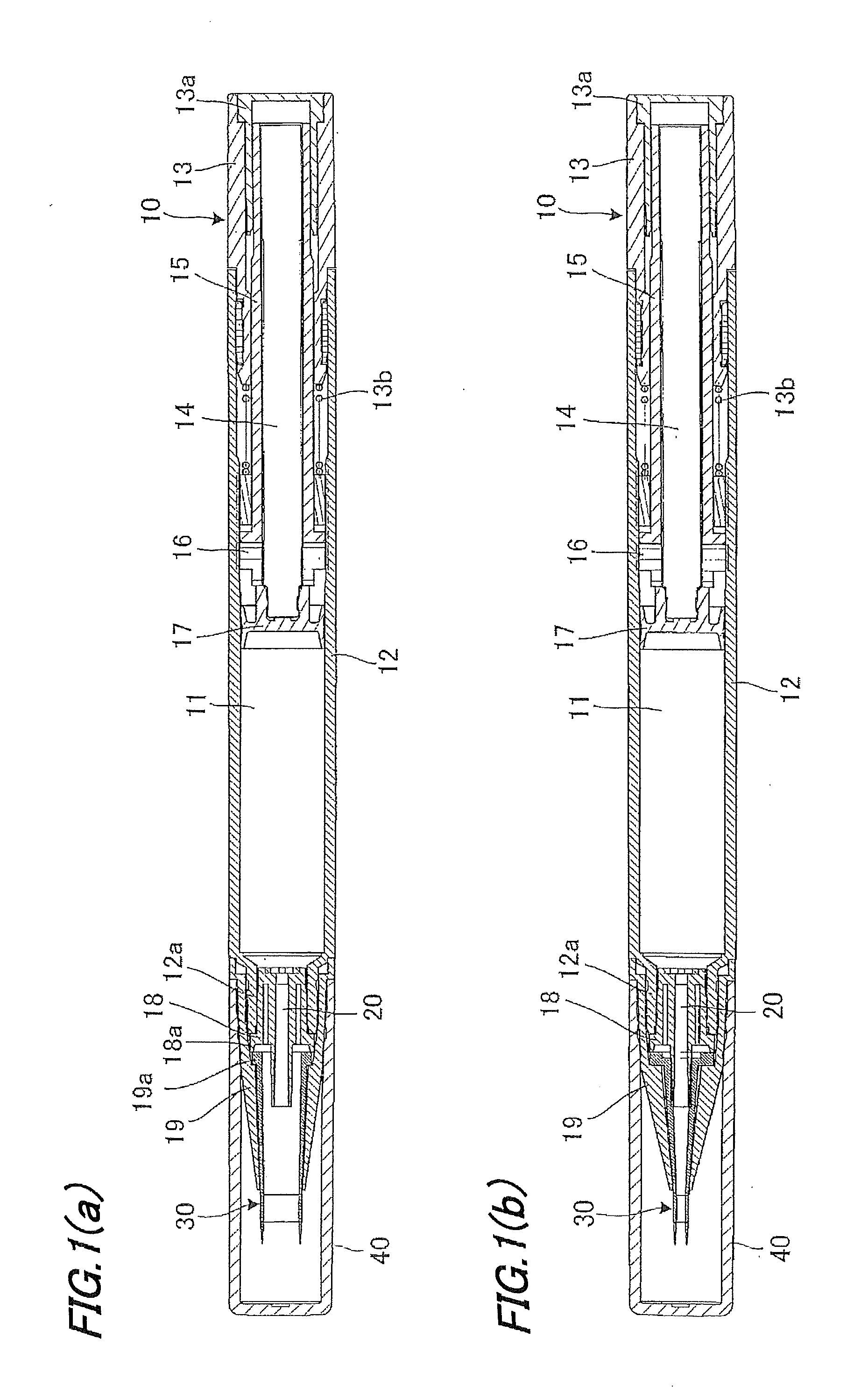
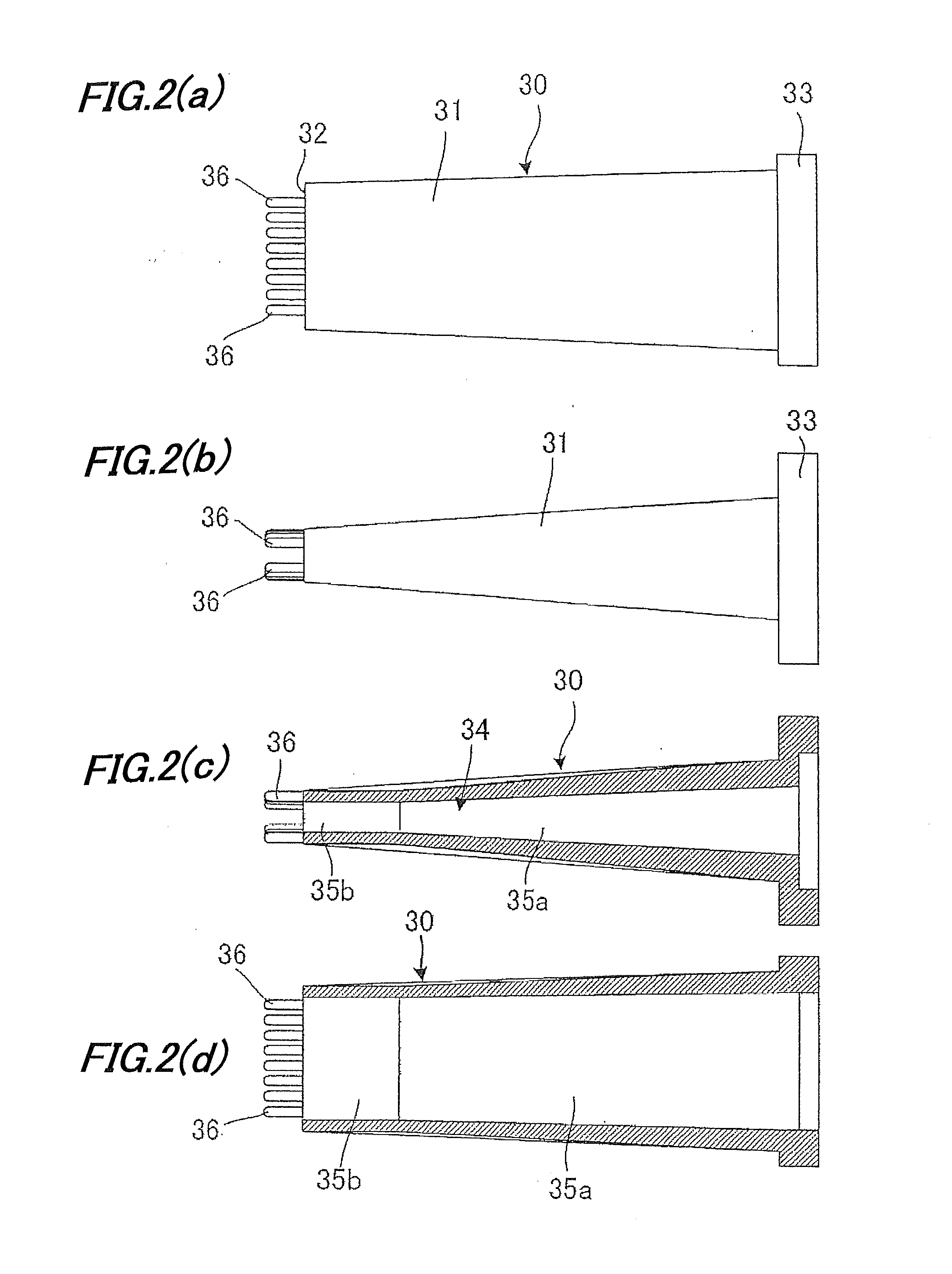
[0081]An applicator was prepared in conformity with FIG. 1, using an applicator part having the following dimensions, based on the FIGS. 1 to 3 below.

(Configuration of Applicator Part)

[0082]Size of the minor axis a: 0.8 mm, the longest direction b: 3.2 mm, the wall thickness around the delivery port: 0.3 mm.

[0083]Eight small-diametric projections were formed of 0.3 mm in outside diameter, 1 mm thick and arranged with a pitch of 0.4 mm. The length of the applicator except the small-diametric projections was 13.5 mm. The load applied when the small-diametric projection was flexed 1 mm was 0.01 N. This applicator part was integrally formed of styrene elastomer (trade name: ACTYMER, a product of RIKEN TECHNOS CORP.).

[0084]As the content liquid, each of liquid cosmetics shown in composition examples 1-7 in Table 1 on a separate sheet, was charged in an amount of 1.4 ml into the applicator.

TABLE 1(Total Amount 100 mass %)Example1234567Coloring MaterialPolyethylene Terephthalate•Polymethyl...


PUM


Abstract

An applicator includes a squeezer for pushing out a content liquid to an applicator part, and the shape of a content liquid delivering port of the applicator part is formed to be oval or rectangular while the minor axis and major axis on the delivery port side are specified to be 0.5 to 2 mm and 2 to 8 mm, respectively. In this applicator, large-sized particles can be delivered by enlargement of the bore inside the applicator part. Further, formation of an oval delivering port allows for drawing fine lines in the minor axis direction and thick lines in the major axis direction. Moreover, provision of small-diametric projections at the front end of applicator, enables drawing of long lines and retaining of the liquid cosmetic stored between projections.

Description

TECHNICAL FIELD[0001]The present invention relates to an applicator used for cosmetics, stationery, daily life commodities and others, such as ink for writing implements and liquid cosmetics.BACKGROUND ART[0002]Conventionally, applicators comprised of a brush, a pen core and resin molding parts have been known.[0003]Of these applicators, there are known ones which include a liquid delivering mechanism that delivers a liquid sent out mechanically (by knocking or thrusting) from a liquid reservoir of the main body by way of a communication pipe connected to the reservoir, to an applicator part connected with the communication pipe. Further, a brush-type applicator has a brush of a tapering (conical) shape, composed of multiple bundles of fiber to perform drawing and application, which provides a supple feature for actions of the writing tip.[0004]However, the brush-type applicator is formed with an aggregate of fiber, or a lump of multiple fibers, so that, in particular, lame particle...

Claims


Application Information

Patent Timeline
IPC IPC(8): B05C1/00
CPCB05C1/00A45D40/262A45D2200/055A45D2200/1072A45D34/00A45D34/04A45D40/20B05C17/01B65D83/00
Inventor UEHARA, JUNYA
Owner MITSUBISHI PENCIL CO LTD
Learn More