Wind turbine

a wind turbine and wind power technology, applied in the field can solve the problems of not providing a really safe and easy access to the known solutions, and achieve the effect of improving the safety of wind power turbines

Inactive Publication Date: 2014-02-20
SIEMENS AG
View PDF6 Cites 11 Cited by
  • Summary
  • Abstract
  • Description
  • Claims
  • Application Information

AI Technical Summary

Benefits of technology

[0007]It is an object of the invention to further improve the safety of wind turbines in pa

Problems solved by technology

None of the known solutions provides a really safe and eas

Method used


Image

  • Wind turbine
  • Wind turbine
  • Wind turbine

Examples


Embodiment Construction

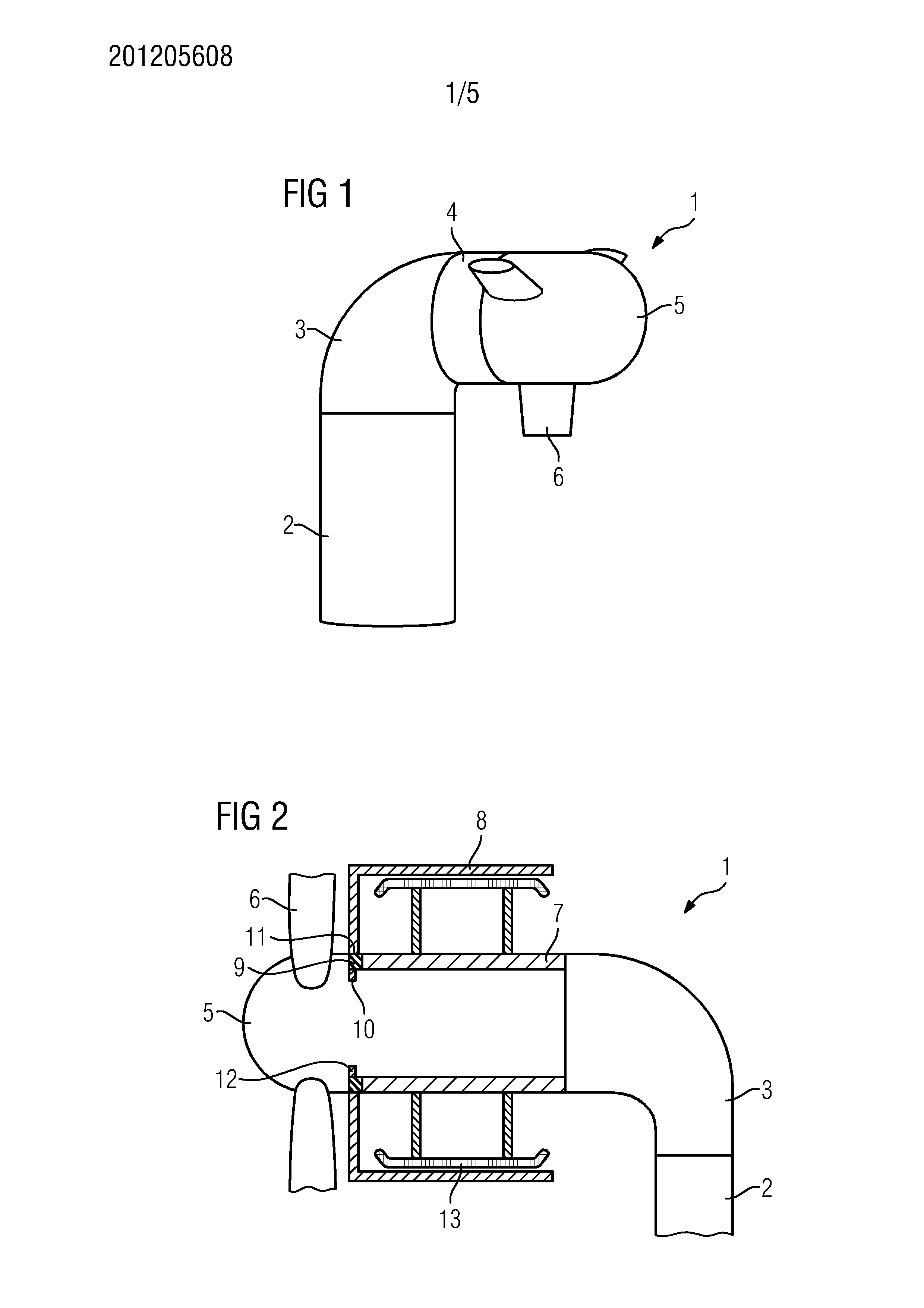
[0030]FIG. 1 shows an inventive wind turbine 1 comprising a tower 2, a bed frame 3, a generator 4 and a rotor hub 5 with several blades 6. The hub serves as an interface between the blades 6 and the generator 4 transferring the torque onto the rotor of the generator.

[0031]FIG. 2 depicts a section through a direct drive wind turbine 1 according to FIG. 1 in the area of the top of the tower 2. The bed frame 3 rests on the tower 2 holding a hollow tubular shaft 7 being part of the generator 4. The generator 4 further comprises a rotor 8 being rotable relative to the stator 7 via a rotor bearing 9 comprising a stationary bearing ring 10 mounted to the hollow stator shaft, while the second running ring 11 of the bearing 9 is fixed to the rotor 8. Furthermore an ovalization ring 12 is shown, also mounted to the front end of the stator shaft. The stator shaft itself is provided with a bunch of stator segments 13 comprising coils, as widely known.

[0032]The rotor 8 is coupled to the hub 5, w...


PUM


Abstract

A wind turbine includes a hollow stator shaft a rotor and a rotor hub. At least one support platform device is provided that facilitates access to the inner of the rotor hub. The at least one platform device includes a first platform which is detachably mounted to a stationary mounting surface facing directly to the inner of the rotor hub.

Description

CROSS REFERENCE TO RELATED APPLICATIONS[0001]The present application claims priority to European Patent Office application No. 12180429.8 EP filed Aug. 14, 2012, the entire content of which is hereby incorporated herein by reference.FIELD OF INVENTION[0002]The invention relates to a wind turbine, comprising a hollow stator shaft, a rotor and a rotor hub, with at least one support platform device facilitating access to the inner of the rotor hub.BACKGROUND OF INVENTION[0003]Wind turbines usually comprise several main components such as blades, hub, generator / drive train, nacelle, bed frame tower and foundation. The hub serves as an adapter piece or interface between the blades and the generator / drive train of the wind turbine. To allow a safe and controllable operation, modern wind turbines comprise a pitch system which allows the adjustment of the angle of attack of the blades, to optimise aerodynamic performance, reduce loads on the wind turbine or induce a stall and cause breaking...

Claims


Application Information

Patent Timeline
IPC IPC(8): F03D1/00
CPCF03D1/003F05B2220/7066F05B2230/80F03D80/50F03D80/80Y02E10/72Y02P70/50
Inventor MUNK-HANSEN, THORKIL
Owner SIEMENS AG
Why Eureka
Try Eureka