
Method and System for Self-Optimized Uplink Power Control

a technology of wireless communication system and power control, applied in power management, radio transmission, electrical equipment, etc., can solve the problems of reducing the data throughput of uplink signals, reducing the power level upon reception, and failing to achieve a globally optimal set of local pc solutions for wireless networks

Active Publication Date: 2014-02-20
HONOR DEVICE CO LTD
View PDF2 Cites 5 Cited by
  • Summary
  • Abstract
  • Description
  • Claims
  • Application Information

AI Technical Summary

Benefits of technology

This patent describes a system and method for optimizing uplink power control in a wireless network. The technical effect of this invention is to provide a more efficient and effective way to control the power of wireless devices in a network, leading to improved overall performance and reliability. This is achieved through a process of natural selection and iterative optimization based on the fitness values of various genes, resulting in a set of optimized power control solutions for each base station in the network.

Problems solved by technology

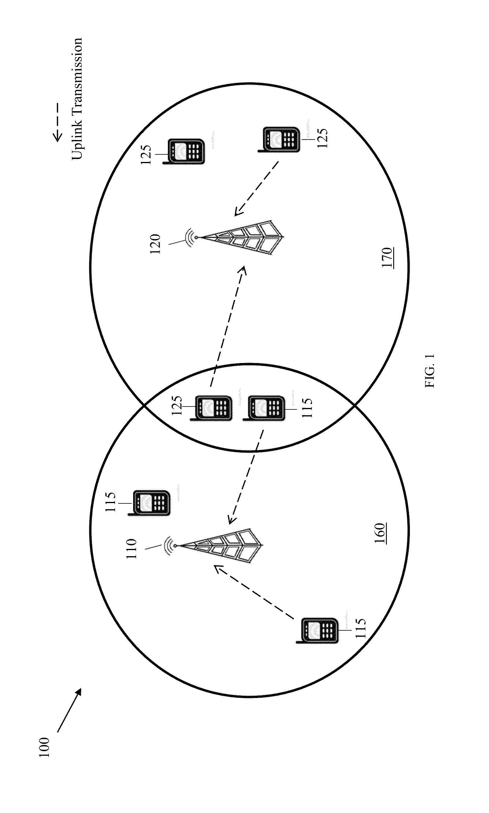
Specifically, uplink transmissions may undergo varying degrees of signal attenuation (e.g., path loss, etc.) as they travel through the PUSCH, and consequently may have a decreased power level upon reception.
However, increasing the transmission power of one uplink signal may also increase the degree to which that uplink signal interferes with other uplink signals in the PUSCH, thereby reducing the data throughput of those uplink signals accordingly.
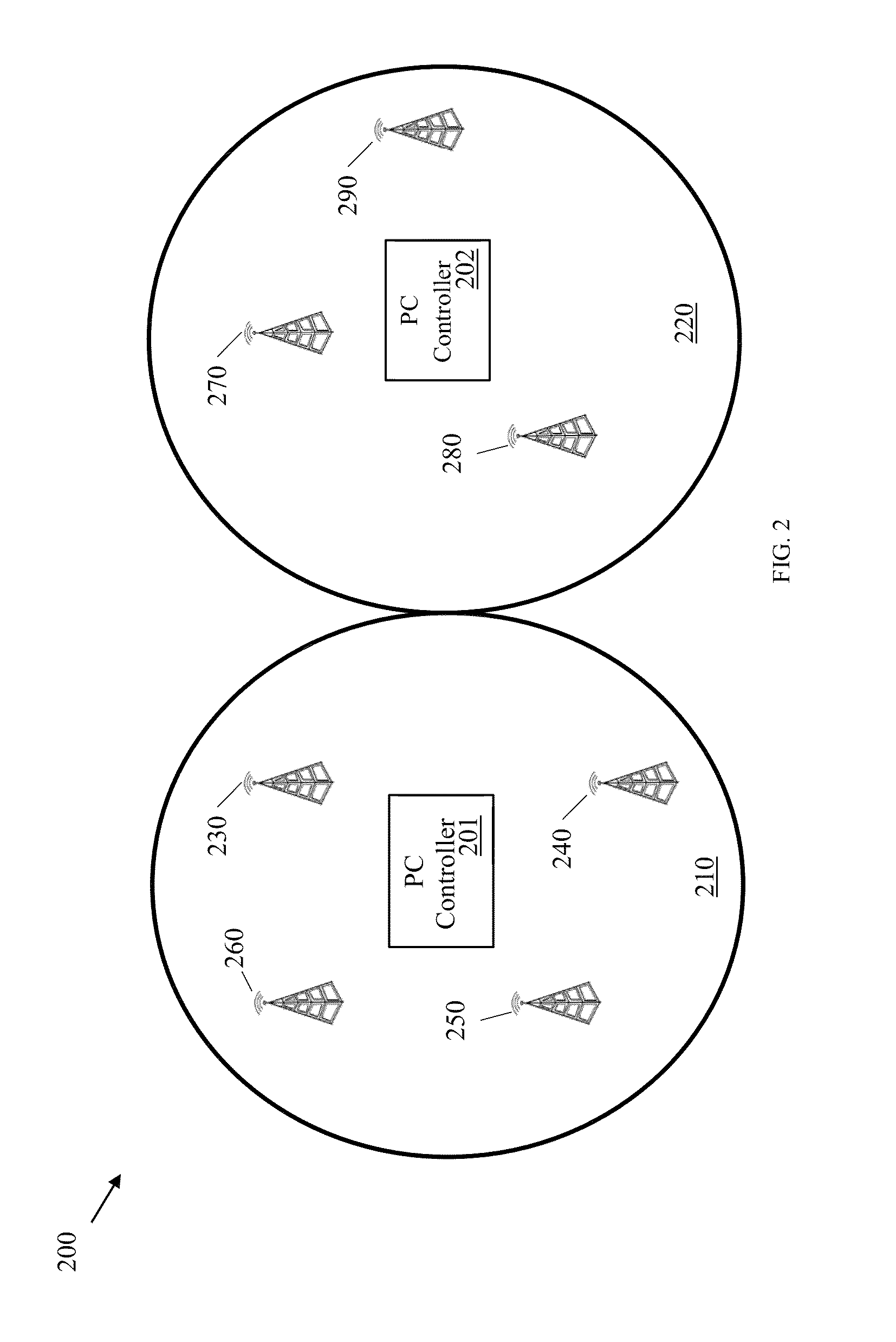
While the gradient search approach may efficiently compute locally optimal PC solutions, it may fail to achieve a globally optimal set of local PC solutions for the wireless network because it may fail to account for the effect each local PC solution will have on neighboring BSs.
Specifically, changing a PC setting for a UE in one coverage area may affect the interference realization of a neighboring base station.
While the exhaustive search approach may effectively compute a globally optimized set of PC solutions, the complex nature of the computation may consume large amounts of network resources (e.g., processing capacity, time, etc.).

Method used


Image

  • Method and System for Self-Optimized Uplink Power Control
  • Method and System for Self-Optimized Uplink Power Control
  • Method and System for Self-Optimized Uplink Power Control

Examples


Embodiment Construction

[0026]The making and using of the presently preferred embodiments are discussed in detail below. It should be appreciated, however, that the present invention provides many applicable inventive concepts that can be embodied in a wide variety of specific contexts. The specific embodiments discussed are merely illustrative of specific ways to make and use the invention, and do not limit the scope of the invention.

[0027]For purposes of clarity and concision, uplink PC solutions will be referred to herein simply as “PC solutions”. As used herein, the term “local PC solution” may refer to a set of PC settings computed for the UEs of a single BS, while the term “global PC solution” may refer to a set of local PC solutions computed for a set of BSs in a wireless network. A “set of locally optimized PC solutions” may refer to a set of local PC solutions that have been computed unilaterally (i.e., irrespective of one another's PC settings), while the term “optimum global PC solution” may ref...


PUM


Abstract

A method for optimizing uplink power control settings in a wireless network, the method comprising generating a first gene pool comprising a set of parent genes, wherein each parent gene comprises a set of first generation power control solutions for a set of base stations in the wireless network. The method may further include performing natural selection on the first gene pool to generate a second gene pool comprising selected ones of the set of parent genes, wherein the selected parent genes are chosen by probabilistically selecting some of the parent genes based on fitness values assigned to the parent genes. The method may further include evolving the second gene pool into a descendent gene, wherein the descendent gene comprises a set of local power control solutions for the set of base station in the wireless network.

Description

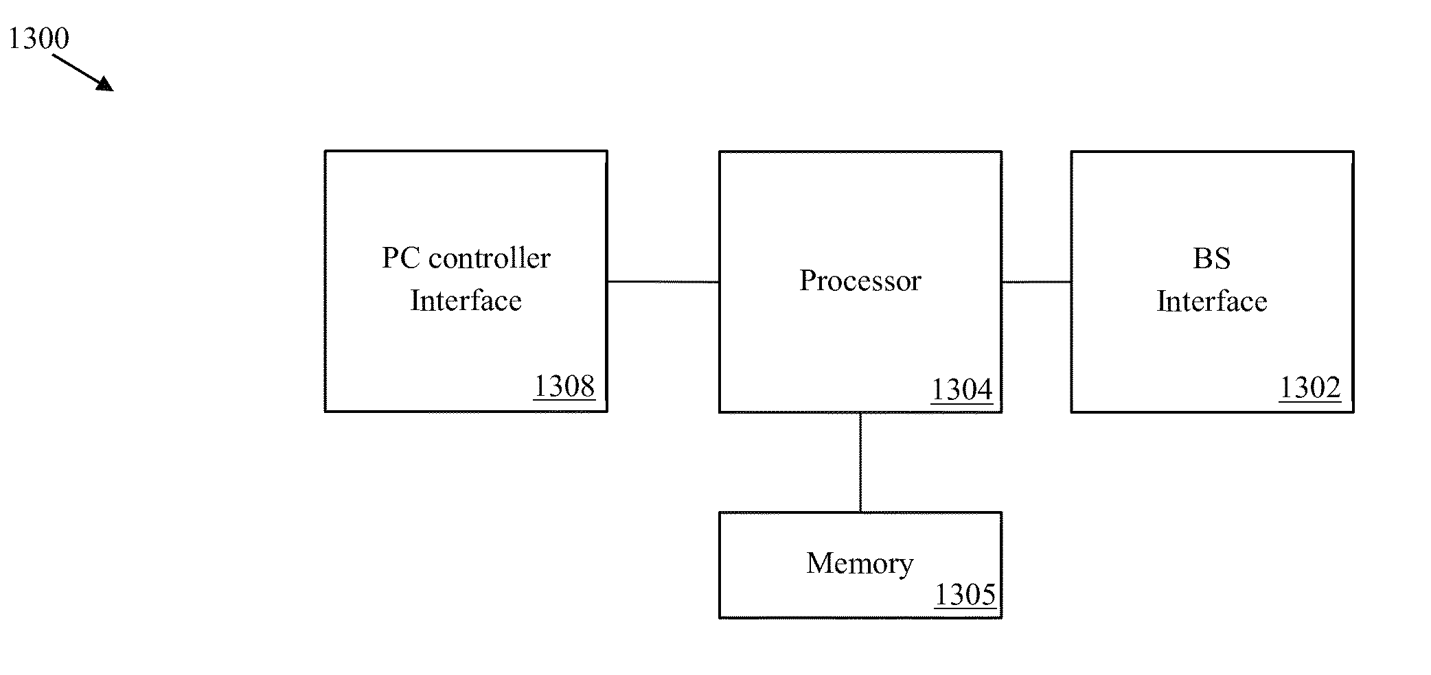
TECHNICAL FIELD[0001]The present invention relates generally to optimizing uplink power control in wireless communication systems.BACKGROUND[0002]Uplink power control (PC) is an important consideration in modern day cellular communication systems that rely on code division multiple access (CDMA) schemes, Orthogonal Frequency-Division Multiple Access (OFDMA) schemes, single carrier frequency division multiple access (SC-FDMA) schemes, etc. to manage uplink communications. Uplink PC may, for instance, control uplink transmissions in the Physical Uplink Shared Channel (PUSCH) of a long term evolution (LTE) wireless network. Specifically, uplink transmissions may undergo varying degrees of signal attenuation (e.g., path loss, etc.) as they travel through the PUSCH, and consequently may have a decreased power level upon reception. The power level of the uplink signals at reception may directly affect throughput such that uplink signals with higher power levels at reception are able to ca...

Claims


Application Information

Patent Timeline
Patent Type & Authority Applications(United States)
IPC IPC(8): H04W52/04
CPCH04W52/225H04W52/243H04W52/40H04W52/146H04W52/267H04W52/06
Inventor CHENG, HO-TINGZHANG, HANG
Owner HONOR DEVICE CO LTD
Learn More