
Image processing device

Inactive Publication Date: 2009-04-23
PANASONIC CORP
View PDF7 Cites 29 Cited by
  • Summary
  • Abstract
  • Description
  • Claims
  • Application Information

AI Technical Summary

Benefits of technology

[0026]With the above-stated structure, the image processing device of the present invention can generate first image data and second image data whose total exposure times are different from each other, for each process target, namely for each set of the predetermined number of frames of image data. Accordingly, in the case where the first time period is a total exposure time shorter than the second time period that is a total exposure time that corresponds to the normal rate, and the first and second image data are generated, it is possible to achieve smooth moving image display by playing back the second image data at the normal rate, and it is possible to achieve display of a clear image with less blurring by performing a slow playback or the like using the first image data.
[0076]With the above-stated structure, when three or more play back speeds (for example, the normal rate, ½ of the normal rate, and ¼ of the normal rate) need to be provided, any time when the receiving unit receives the instruction specifying a playback speed after change that is greater than the first threshold value being ½ of the normal rate, the playback is switched to a playback of the second image data only when the playback speed specified in the instruction is equal to or greater than the second threshold value (for example, the normal rate) that is greater than the first threshold value. Accordingly, even when an instruction to switch to a playback speed near the first threshold value is frequently received, the display is not switched. This enables the process load for the switching process to be reduced.

Problems solved by technology

A problem recognized in such a case is that a blurred image is displayed when a moving image of a fast moving object is played back slowly.
With the combined technology, however, it is not possible, at an arbitrary timing, to switch the display from a playback of moving image data at the normal rate to an image with less object blurring (for example, a slow playback).

Method used


Image

  • Image processing device
  • Image processing device
  • Image processing device

Examples


embodiment 1

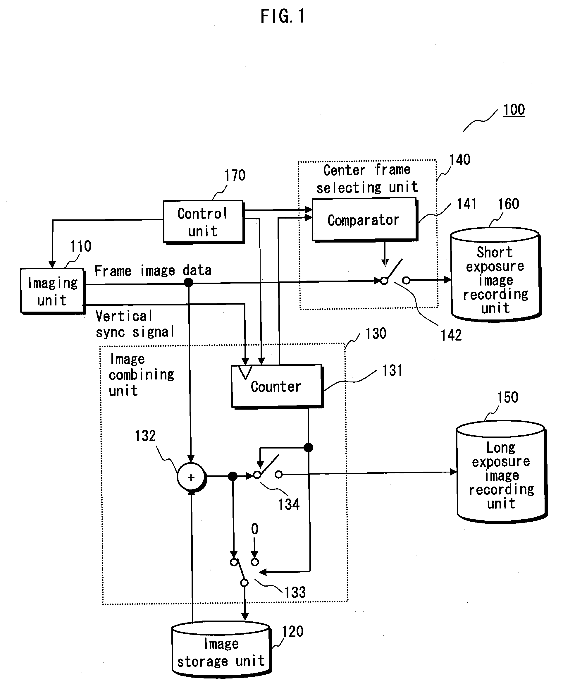
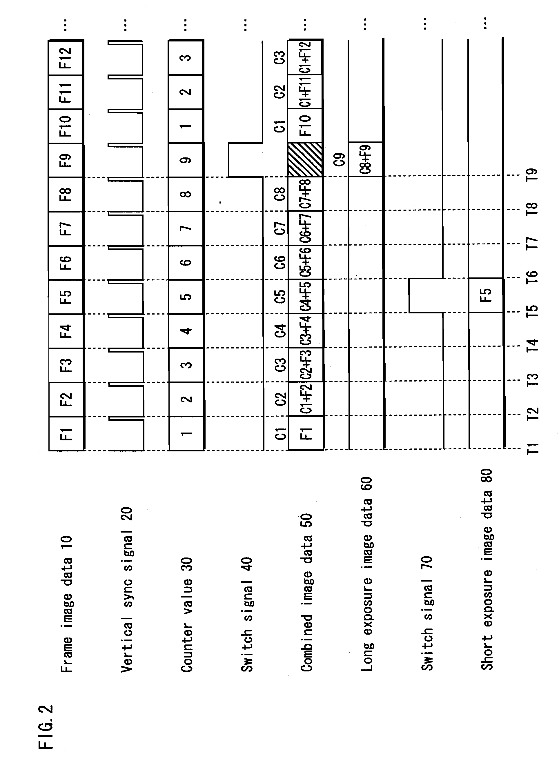
[0097]The image processing device of Embodiment 1 is an improvement of a conventional image processing device (imaging device) having an image taking function. The image processing device of Embodiment 1 obtains frames of image data in sequence as it takes images of an object, and by using the obtained image data, it generates two types of moving image data that are composed of frames of image data with two different exposure times.

[0098]The image processing device of Embodiment 1 obtains frames of image data in sequence as it takes images of an object with a predetermined exposure time. The image processing device of Embodiment 1 then performs the following process for each predetermined number of frames of image data (hereinafter, the predetermined number is referred to as “combination number”) in sequence in order of image taking. The combination number may be any number, but is “9” for example.

[0099]More specifically, the image processing device of Embodiment 1 generates image d...

embodiment 2

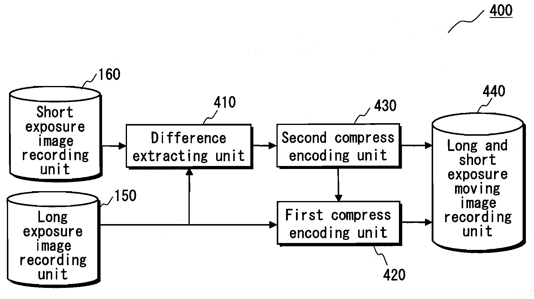
[0176]The image processing device of Embodiment 2 is an improvement of a conventional image processing device (moving image encoding device) that supports the MPEG-4 AVC (Moving Picture Expert Group-4 Advanced Video Coding) standard, and generates a plurality of encoded data sequences in the format of MPEG-4 AVC by compress encoding a plurality of sets of image data.

[0177]More specifically, the image processing device of Embodiment 2 compress encodes the long exposure image data and the short exposure image data generated by the image processing device 100 of Embodiment 1 as follows: the image processing device of Embodiment 2 detects motion vectors of each piece of short exposure image data, and compress encodes each piece of short exposure image data and corresponding pieces of long exposure image data using the detected motion vectors.

[0178]That is to say, the conventional image processing device detects motion vectors from the long exposure image data and the short exposure imag...

embodiment 3

[0211]The image processing device of Embodiment 3 is an improvement of a conventional image processing device (playback device) that plays back encoded data sequences in the MPEG-4 AVC format, and can perform playback at different playback speeds by switching between different types of encoded data sequences to be read out for the playback, namely by switching between encoded long exposure image data sequences and encoded short exposure image data sequences, which are both in the MPEG-4 AVC format and are generated by the image processing device 200 in Embodiment 2.

[0212]More specifically, to playback at a normal rate, the image processing device of Embodiment 3 reads out encoded long exposure image data in sequence in order of playback from the encoded data sequences in the MPEG-4 AVC format so that the decoded long exposure image data are displayed in sequence. This enables the moving image to be displayed smoothly.

[0213]Further, upon receiving, from the user, a playback speed swi...


PUM


Abstract

An image processing device comprising: an imaging unit outputting frames of image data sequentially in order of imaging; a first generation unit generating first image data sequentially in units of a predetermined number of consecutive frames of image data, from the output frames of image data, wherein a total exposure time of each piece of first image data is a first time period; a second generation unit generating second image data sequentially in units of the predetermined number of consecutive frames, from the output frames of image data, a total exposure time of each piece of second image data is a second time period different from the first time period; and an output unit outputting each pair of first image data and second image data generated from a same set of the predetermined number of consecutive frames of image data, in correlation with each other.

Description

BACKGROUND OF THE INVENTION[0001](1) Field of the Invention[0002]The present invention relates to a technology of processing moving image data, specifically to a technology of generating a plurality of pieces of moving image data and a technology of compress encoding and playing back each piece of moving image data.[0003](2) Description of the Related Art[0004]Normally, frames of image data that constitute the moving image data are generated with an exposure time that corresponds to the frame rate at which the moving image is played back (hereinafter, the frame rate is referred to as “normal rate”).[0005]When, for example, the normal rate is 30 fps (frames per second), each frame of image data is generated with an exposure time of approximately 1 / 30 seconds. When the moving image data obtained in this way is played back at the normal rate, the displayed moving image appears to move smoothly.[0006]Meanwhile, the moving image data obtained in this way may be played back at a rate diff...

Claims


Application Information

Patent Timeline
IPC IPC(8): H04N7/26G06T3/00G06T5/20G06T5/50H04N5/225H04N5/228H04N5/232H04N5/235H04N5/91H04N5/93H04N19/00H04N19/132H04N19/196H04N19/31H04N19/50H04N19/503H04N19/51H04N19/58H04N19/587H04N19/80
CPCH04N5/772H04N19/39H04N5/91
Inventor FUCHIKAMI, RYUJIFUCHIGAMI, IKUOTEZUKA, TADANORI
Owner PANASONIC CORP
Learn More