Crowbar disconnect switch

a technology of disconnect switch and cable, which is applied in the direction of air break switch, high-tension/heavy-dress switch, electrical apparatus, etc., can solve the problems of unnecessarily losing power in even the feeder circuit and considerable damage done by the energy being dispersed, and achieve the effect of reducing damage to downstream equipmen

Active Publication Date: 2014-02-27
SCHNEIDER ELECTRIC USA INC
View PDF6 Cites 6 Cited by
  • Summary
  • Abstract
  • Description
  • Claims
  • Application Information

AI Technical Summary

Benefits of technology

[0005]In one implementation, each feeder circuit is provided with a separate disconnect switch that responds to the detection of an arcing fault condition in that feeder circuit to instantly interrupt the supply of power to that feeder circuit while also transferring the fault current to the disconnect switch where any arcing is quickly controlled and extinguished within a protected cavity. The instant isolation of the feeder circuit in which the fault occurred reduces damage to downstream equipment, while the arc suppression protects both equipment and personnel from damage or injury that might otherwise be caused by the arcing.

Problems solved by technology

During this delay, considerable damage can be done by the energy being dissipated from the event that triggered the short.
If the main circuit breaker trips before the circuit breaker of the feeder circuit in which the fault occurred, power can be unnecessarily lost in even the feeder circuits that were not affected by the fault condition.

Method used


Image

  • Crowbar disconnect switch
  • Crowbar disconnect switch
  • Crowbar disconnect switch

Examples


Embodiment Construction

[0015]Although the present disclosure is described in connection with certain aspects and / or embodiments, it will be understood that the present disclosure is not limited to those particular aspects and / or embodiments. On the contrary, the present disclosure is intended to cover all alternatives, modifications, and equivalent arrangements as may be included within the spirit and scope of the present disclosure as defined by the appended claims.

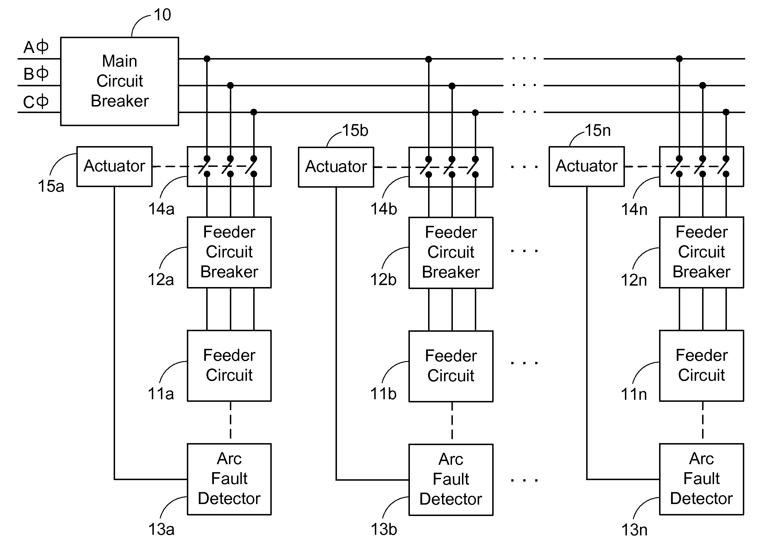
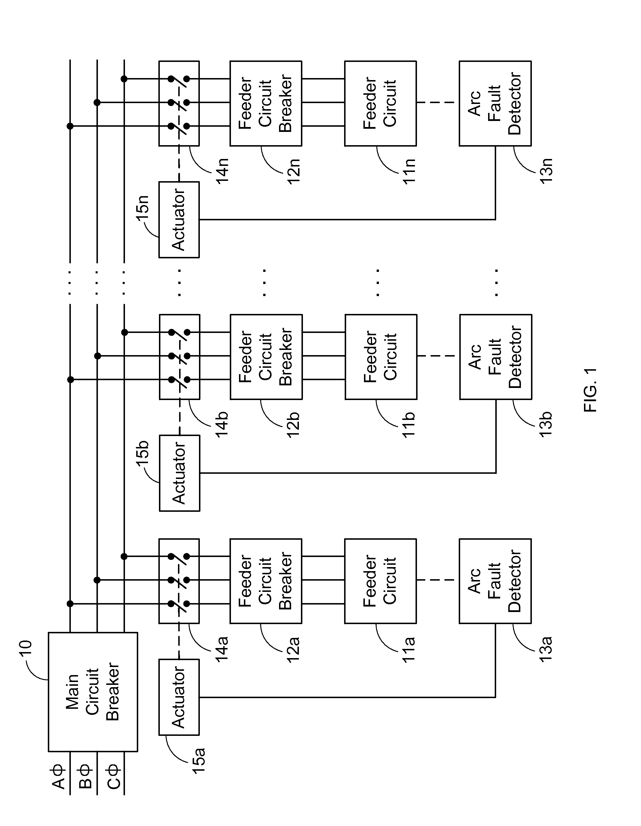
[0016]Turning now to the drawings and referring first to FIG. 1, one embodiment of the invention is illustrated in the context of a three-phase power distribution system that supplies three-phase power from a source through a main circuit breaker 10 to multiple branch or “feeder” circuits 11a, 11b . . . 11n via respective feeder circuit breakers 12a, 12b . . . 12n. Each of the feeder circuits 11a, 11b . . . 11n is coupled to one of a set of arc fault detectors 13a, 13b . . . 13n that detect the occurrence of arcing faults in the respective fee...


PUM


Abstract

A three-phase disconnect switch for a power distribution system that supplies three-phase power from a source through a main circuit breaker to multiple three-phase feeder circuits, includes three pairs of contacts adapted for connection to the three phase lines of a selected one of the feeder circuits for opening and closing each of the phase lines, and a movable actuator associated with the three pairs of contacts and responsive to a signal indicating the occurrence of an arcing fault in the selected feeder circuit for initially creating a short circuit across the three phase lines of the feeder circuit and then opening the contacts.

Description

FIELD OF THE INVENTION[0001]The present invention relates generally to electrical power distribution systems and, more particularly, to protecting feeder circuits in a multi-phase power distribution system from arcing faults while also containing the arcing, dissipating the fault current to extinguish the arcing, and isolating the feeder circuit in which the fault occurred.BACKGROUND OF THE INVENTION[0002]Typical devices used to reduce available energy from an arc flash event, over-current event or arc fault will short out the electrical circuit while waiting for an upstream circuit to open and isolate the circuit. During this delay, considerable damage can be done by the energy being dissipated from the event that triggered the short.[0003]When multiple feeder circuits are supplied with power from a common supply bus, circuit breakers are typically provided in each of the feeder circuits in addition to the main circuit breaker in the common supply bus. If the main circuit breaker t...

Claims


Application Information

Patent Timeline
Patent Type & Authority Applications(United States)
IPC IPC(8): H01H33/04H01H33/02
CPCH01H79/00H01H33/022H01H33/06H01H33/12
Inventor WEIDEN, CONRAD
Owner SCHNEIDER ELECTRIC USA INC
Why Eureka
Try Eureka