
Switching Valve

Inactive Publication Date: 2014-02-27
GLOBE UNION INDAL
View PDF7 Cites 18 Cited by
  • Summary
  • Abstract
  • Description
  • Claims
  • Application Information

AI Technical Summary

Benefits of technology

The present invention provides a switching valve with improved design that overcomes the shortcomings of conventional valves. The valve has a cylindrical plug member that eliminates inner chambers and orifices, reducing production costs. The plug member has guiding ribs and slots to smoothly flow water and stabilize water supply. It also has stop blocks to prevent leakage and a gap to enhance water capacity. A damping spring stabilizes the operation of the plug member for changing water supply from the faucet assembly. The side fence has a hole to prevent turbulence and ensure smooth operation of the plug member. The overall design achieves improved operational efficiency and sufficient water capacity.

Problems solved by technology

1. The plug member is hollow so that a chamber is defined in the plug member and two sets of holes formed around the chamber so as to flow water. But the plug member is metal formed and machined at high cost.
2. The upper O ring is forced by the water pressure, thus causing a deformation. In addition, water leaks from the gap between the upper O ring and the upper valve seat easily, thus having a water leakage from the faucet assembly.
3. As changing water supply from a faucet mode to a spray head mode, the plug member moves to the spray head quickly, so the upper O ring of the plug member collides the upper valve seat to result in vibration and noises.
4. As changing water supply from a spray head mode to a faucet mode, the flow capacity decreases to cause a back pressure, so the plug member switches to the spray head and the faucet assembly, hence the plug member swings constantly.

Method used


Image

  • Switching Valve
  • Switching Valve
  • Switching Valve

Examples


Embodiment Construction

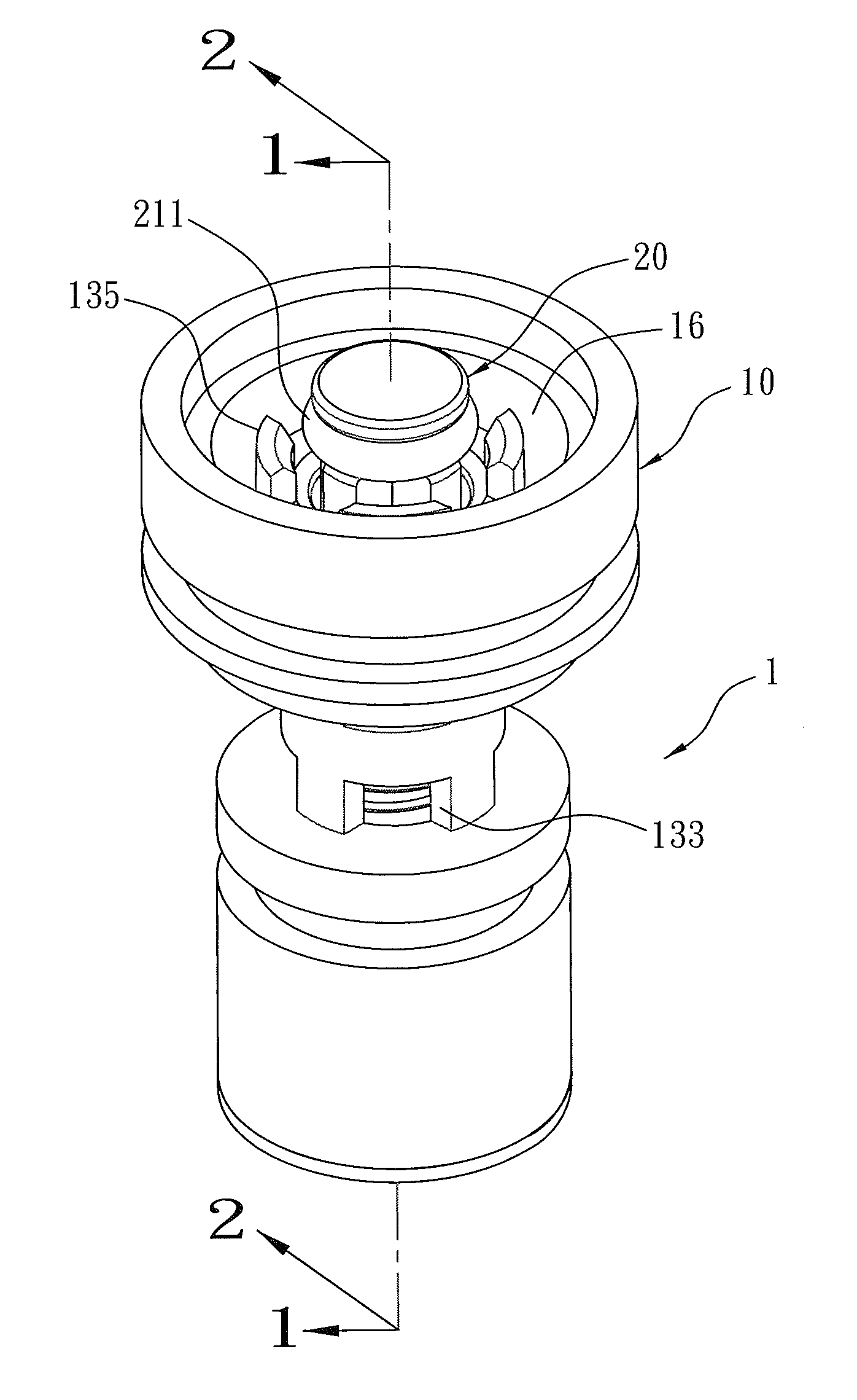
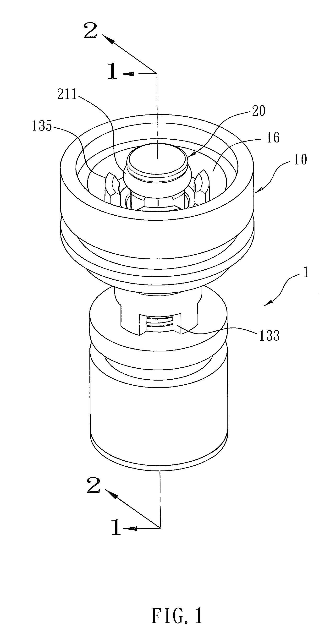
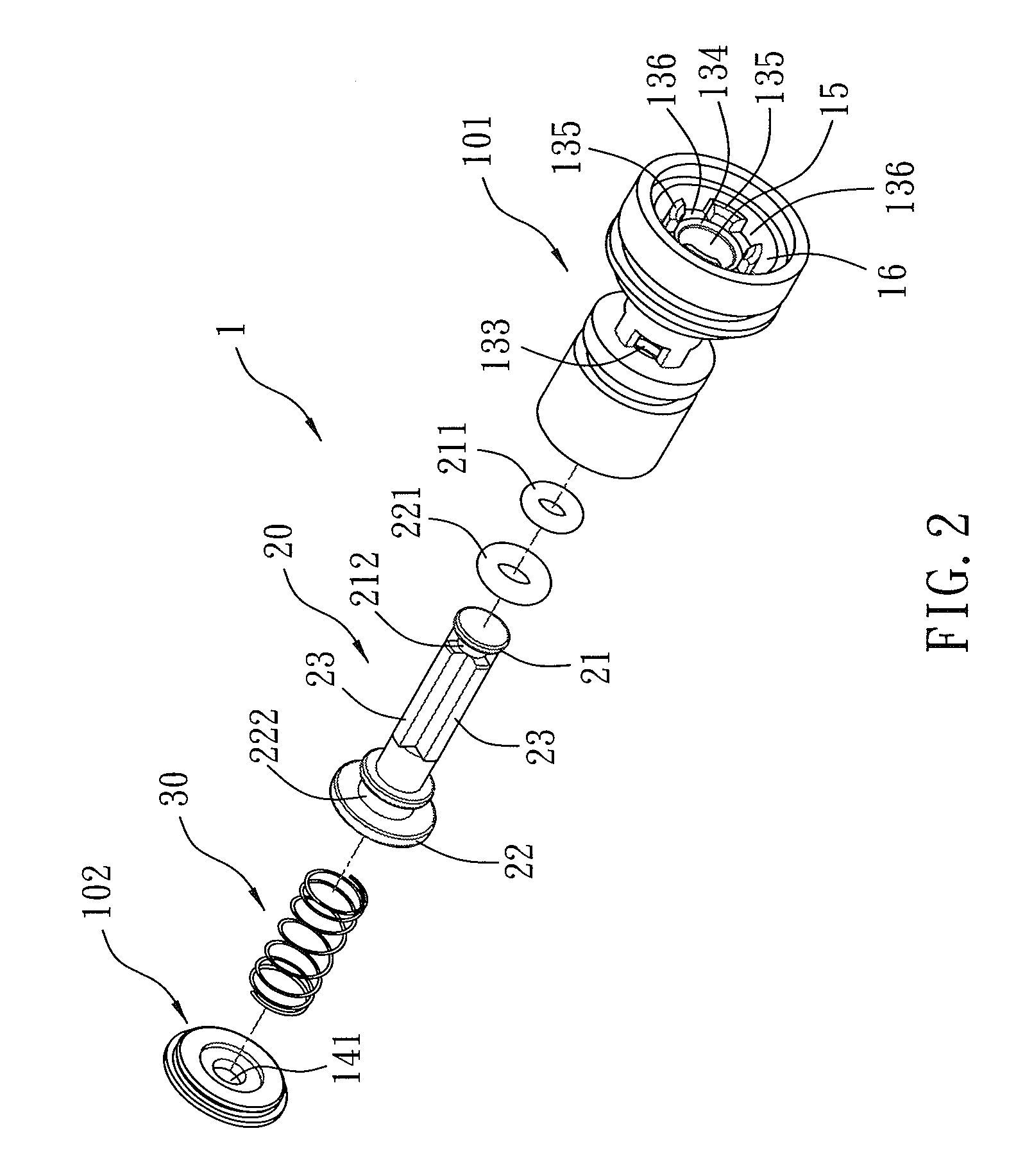
[0029]Referring further to FIGS. 1-4, a switching valve 1 according to a preferred embodiment of the present invention comprises: a sleeve member 10, a plug member 20, and a damping spring 30.

[0030]As shown in FIG. 5, the sleeve member 10 is cylindrical and includes a watering segment 11, a spraying segment 12 opposite to the watering segment 11, a peripheral fence 13, a side fence 14 connecting with the peripheral fence 13 and defined on the spraying segment 12, a channel 15 defined between the peripheral fence 13 and the side fence 14, a first watering chamber 16 communicating with the channel 15 and formed adjacent to the watering segment 11, and a second watering chamber 17 communicating with the channel 15 and formed proximate to the spraying segment 12. The peripheral fence 13 has a first valve seat 131 arranged on a connection of the channel 15 and the first watering chamber 16, a second valve seat 132 formed on a connection of the channel 15 and the second watering chamber 1...


PUM


Abstract

A switching valve contains a sleeve member, a plug member, and a damping spring. The sleeve member includes a watering segment, a spraying segment, a peripheral fence, a side fence, a channel, a first watering chamber, and a second watering chamber. The peripheral fence has a first valve seat, a second valve seat, and at least one set of inlet. The first valve seat has a conical first closing face and a plurality of stop blocks. The second valve seat has a conical second closing face. The plug member includes a first sealing portion, a second sealing portion, and guiding ribs. The first sealing portion has a first ring, and the second sealing portion has a second ring. Each guiding rib has a guide face, and between any two adjacent guiding ribs is defined a slot. The damping spring is mounted between the side fence and the plug member.

Description

FIELD OF THE INVENTION[0001]The present invention relates to switch valve.BACKGROUND OF THE INVENTION[0002]CN Patent No. 201606557U discloses that a conventional switching valve is installed in a body of a faucet assembly. The conventional switching valve includes a sleeve member and a plug member sliding along the sleeve member. In a normal operation state, water flows out of an outlet of the faucet assembly via the sleeve member, the plug member, a gap between an upper O ring and an upper valve seat of the plug member. Accordingly, when a lever of a spray head is operated, a water pressure in the switching valve changes so that the plug member slides downward, such that the upper O ring is biased against the upper valve seat, thus stopping a water supply from the faucet assembly. In the meantime, the water flows to the spray head through the sleeve member and a clearance between a lower O ring and a lower valve seat.[0003]However, such a conventional switching valve still has the ...

Claims


Application Information

Patent Timeline
IPC IPC(8): F16K1/34
CPCF16K1/34F16K11/048E03C2201/30Y10T137/2683Y10T137/86895Y10T137/87861
Inventor CHANG, CHUNGHSIANGKUO, CHUNGYU
Owner GLOBE UNION INDAL
Learn More